Dell PERC 3/DC / MegaRAID Elite 1600 Battery Replacement

Updated 6-Apr-2012: BatteryPrice no longer lists the HF-C1U battery. Please refer to my comment at the end of this post for more information.

The Dell PERC 3/DC RAID controller (a re-branded MegaRAID Elite 1600) was a very popular RAID controller on older server systems. Here is a picture of the Dell version:
PERC 3/DC board

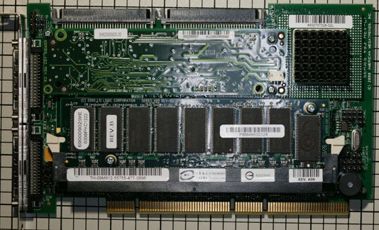
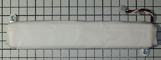
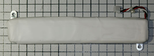
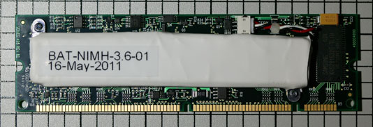
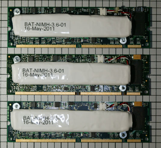
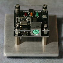
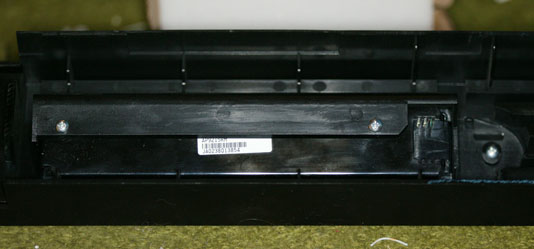
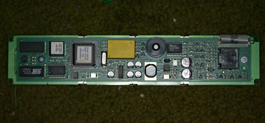
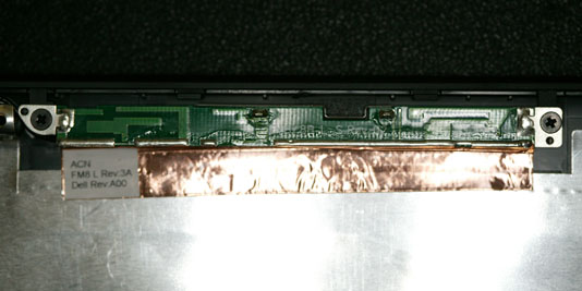
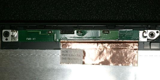
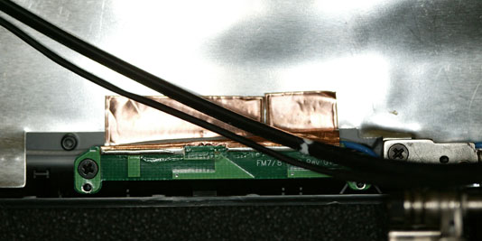
This controller was available with two different battery backup options – the normal “Battery Backup Unit” (BBU), and a “Transportable BBU” which was mounted on the back of a custom memory module. For some reason, Dell PERC 3/DC cards have both the regular BBU and the transportable one installed, but the battery is only installed on the transportable BBU. All of the 50 or so of these controllers that I’ve seen have both installed. The battery on the memory module gives new meaning to the term “Battery Backed RAM”:
Battery Backed RAM module

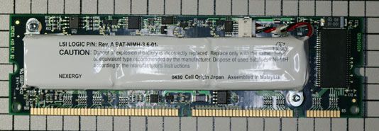
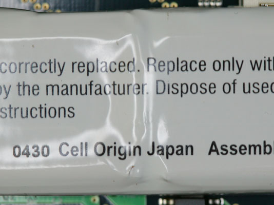
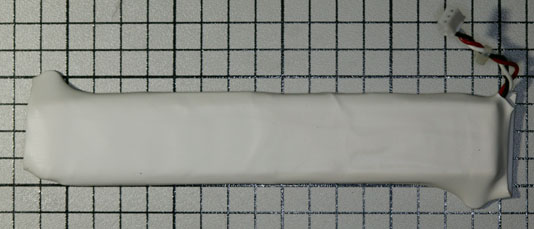
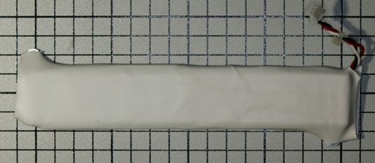
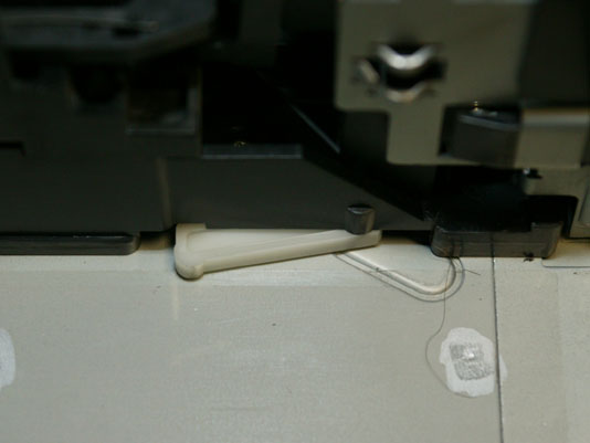
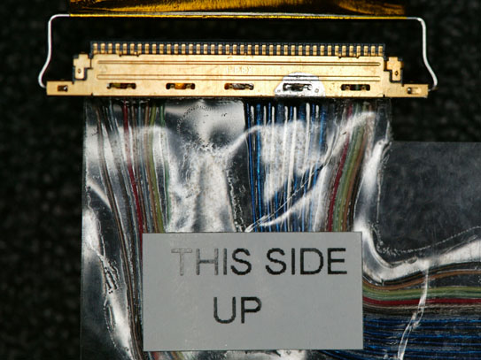
Unfortunately, these batteries are well past their useful service life. They no longer hold a charge and many have started to leak. Take a look at the bottom center of the white plastic wrapper in this picture:
Leaking Battery

Several years ago, I contacted LSI Logic (who purchased the MegaRAID product line from AMI a long time ago). Unfortunately, they could no longer provide the battery module as it was an obsolete part. At the time, I was able to salvage batteries from my spare controllers (or so I thought – more on this in a bit) and use them on my production boards.

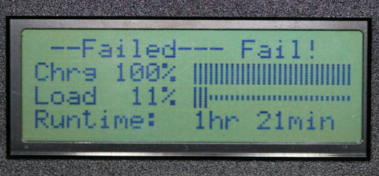
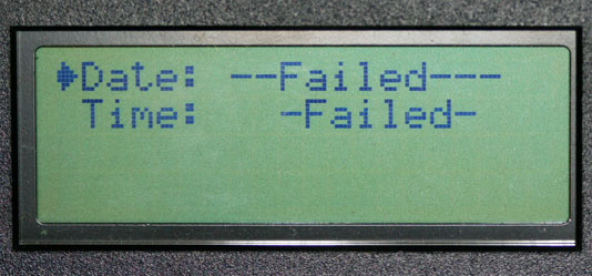
Recently, I had a number of systems start reporting “Charge failed” or “Battery pack missing” for their battery status. So I began investigating replacement batteries again.

I contacted the original manufacturer (Nexergy) as well as a number of custom battery pack manufacturers. Unfortunately, all of the ones that replied stated that they could not produce the battery pack. Nexergy said “This is an obsolete part and the cell you have as well as the tooling to make the pack is no longer available to us.

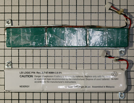
The only references I could find on the Web, searching for the part numbers on the battery – 4920100000 or BAT-NIMH-3.6-01 – were from other people looking for replacement batteries, or from companies wanting to sell used controllers (which would also have bad batteries on them).

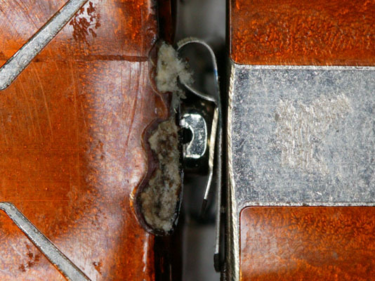
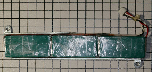
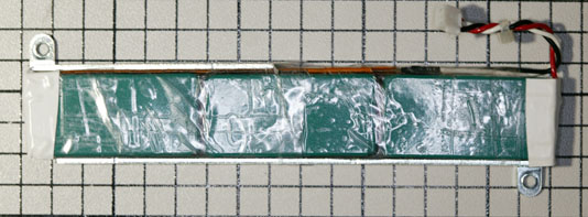
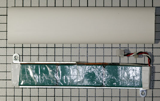
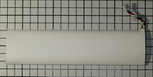
Therefore, I decided that if I wanted to have working battery backup packs, I would need to make replacements myself. My first step was to remove the battery from the memory module and un-wrap the outer whiite plastic casing:
Inside of battery pack

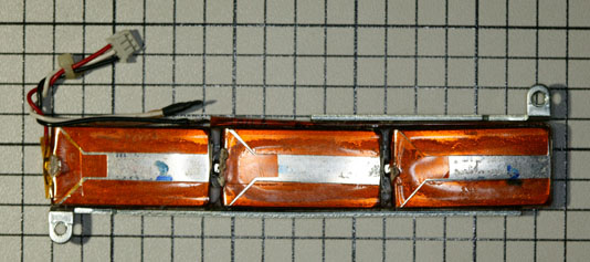
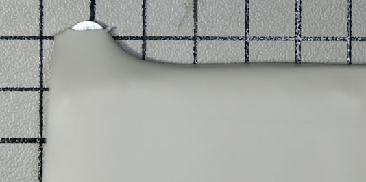
As I had suspected, there was a lot of corrosion where the chemicals had leaked out of the battery:
Corroded batteries

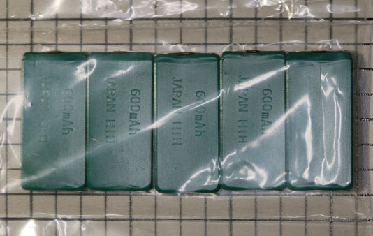
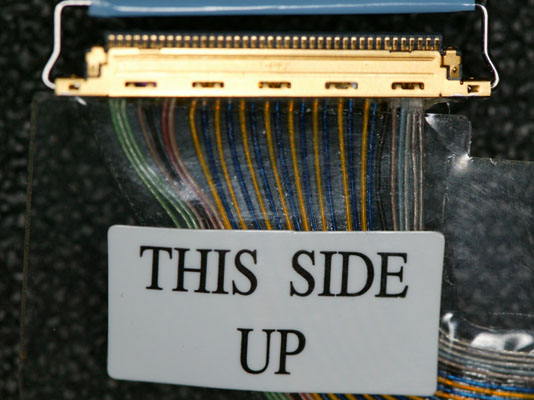
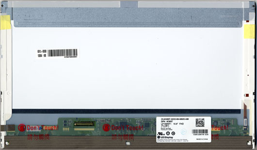
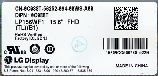
Fortunately, I was able to determine that the actual batteries inside the module were of a standard size, known as a HF-C1U (PDF spec sheet here). That meant that I could purchase replacement cells and assemble a new module by re-using the existing brackets and wiring harness.

The HF-C1U battery is becoming difficult to find, as it is nearly obsolete. I located a large quantity at a company called BatteryPrice. They also offered the batteries with an option to have solder tabs installed on the batteries. It is important to get batteries with this option, as the normal variety without the tabs will be impossible to solder. I placed an order for batteries and they arrived in two days:
Bag of replacement batteries

If you decide to perform this repair yourself, I suggest you order additional batteries as you may damage some when soldering them.

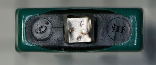
I soldered three of the batteries together, with the positive terminal of one to the negative terminal of the next one. It is important to have the correct polarity. One end of the battery will be a solid metal plate – that’s the negative end. The positive end will have a small metal button on a mostly-plastic plate. Here’s a view of the positive end, with the solder tabs bent up to provide clarity:
Positive end of battery

Next, I used clear plastic shipping tape to hold the 3 new batteries together, by wrapping each of the 2 connections with tape:
Batteries taped together

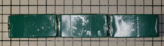
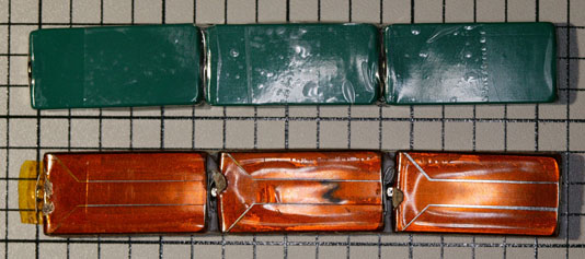
Here is a comparison of the old string of batteries and my new set:
Old vs. new batteries

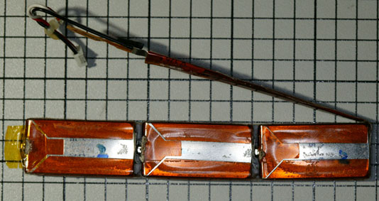
Next, I carefully removed the cable and strap from the old battery pack. The red wire was unsoldered, which let me lift up the whole assembly from the string of batteries. The strap is spot-welded to the end of the old batteries, so I peeled it back and carefully cut it off to leave as much of the strap as I could, for soldering onto the new batteries:
Lead on batteries

Lead removed from old batteries

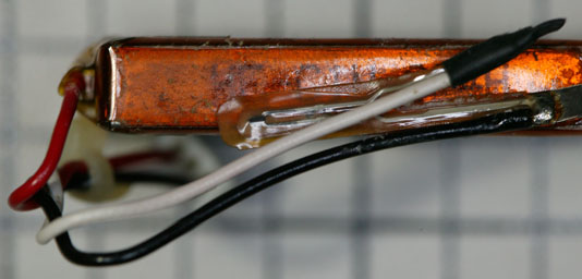
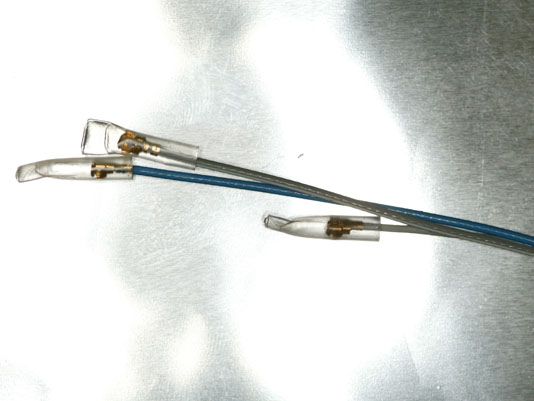
In addition to the wires and the strap, there is a thermistor (thermal sensor) which the controller uses to limit the charge rate of the battery. Here is a close-up view – the thermistor is the angled piece connected to the white and black wires:
Thermistor

After removing the old cable and strap assembly, I soldered it onto the new string of batteries. The red wire connects to the positive terminal, and the end of the strap connects to the negative terminal at the other end of the new string. I then used more clear plastic shipping tape to mount the two metal brackets and to hold the thermistor close to the side of the battery pack:
New batteries all wired

Here is a comparison of the old and new batteries. It is important to correctly position the brackets so that the spacing between the holes is the same as on the old battery, and that the brackets are aligned with the back edge of the batteries so there is no gap between the brackets and the circuit board when installed:
Old vs. new batteries

The next step is to enclose the completed battery pack in an insulating material. The original wrapper was unusable, as I had to cut it in order to remove it. I decided on a combination of electrical tape and heat shrink tubing. A complete wrap with electrical tape would probably work as well, but wouldn’t look as nice.

The first step is to use electrical tape to cover both ends of the battery pack, since the heat shrink tubing will leave that area exposed:
Ends taped

Next, I cut a piece of 3/4″ diameter heat shrink tubing (3M part number 5174-1345, available from Mouser Electronics). The tubing is slightly longer than the battery pack. We will rely on this in order to shrink the ends:
Next to heat shrink tubing

I cut a small notch in one end of the tubing to accomodate the power cables and slid the battery pack into the tubing:
In heat shrink tubing

Next, I used a heat gun (a hair dryer would also work) to start shrinking the tubing onto the battery pack. It is important to go slowly to avoid overheating the batteries, which could damage them:
Partially shrunk tubing

I used a razor blade to carefully remove a small piece of the tubing where it was pulled against each mounting tab:
Tabs trimmed

Here is a close-up of the tubing cut at the tab:
Close-up of trimmed tab

I then used the heat gun to complete the shrinking of the tubing, which fully exposed the tabs:
Tabs exposed

In the previous picture you can see the extra heat shrink tubing on both ends of the battery. The next step is to trim that down to a reasonable amount:
Excess tubing trimmed

Now we’re finally ready to mount the battery on the memory module. Because the heat shrink tubing is a bit thicker than the original wrapper, we need to add some spacers between the circuit board and the battery at each of the two screw locations. The best bet would be some nylon spacers, but I only had metal ones. If you use metal ones, make sure they’re small enough to not short out any of the wiring on the circuit board. I also made up a label with the part number and date of assembly:
Battery installed on module

I went ahead and made a number of additional battery packs so I could get them charged before replacing the bad batteries in my systems:
3 completed batteries

The batteries are shipped in a partially-charged state, normally about .8 volts compared to the labeled 1.2 volts. I made a simple power adapter using two pieces of solid CAT 5 wire, so I wouldn’t have to poke around on the memory module itself:
Test adapter

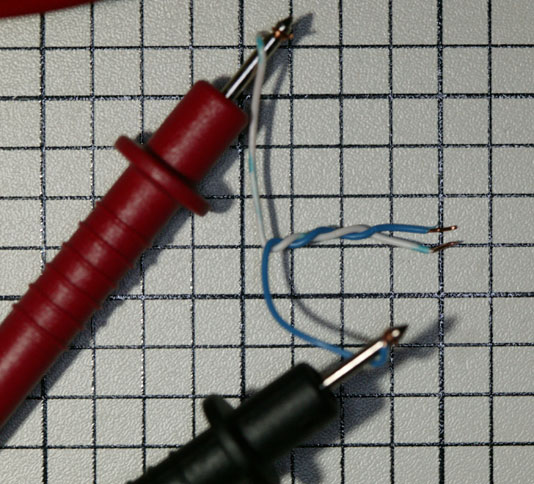
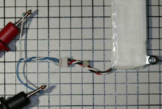
Here is how the adapter is used:
Adapter and battery

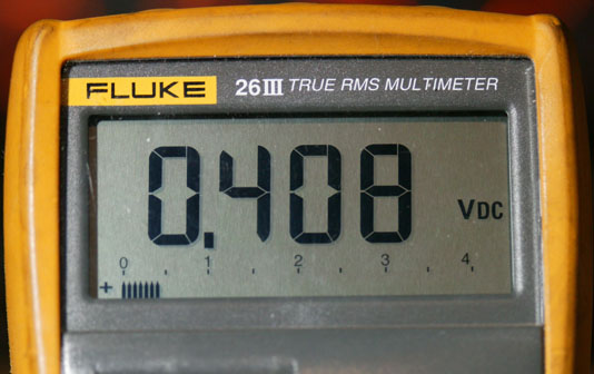
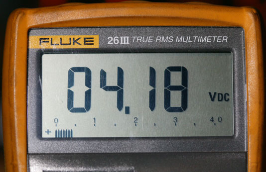
This is the reading from one of the dead original battery packs, showing a voltage of approximately 0.4 volts. This battery has been discharged beyond recovery and can never be recharged:
Dead battery

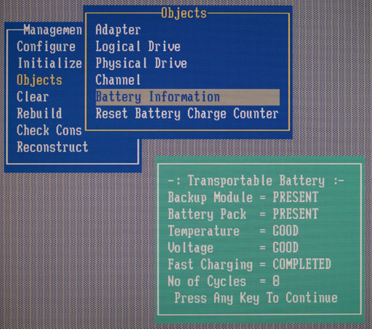
It is important to note that the system this battery was used in (both the controller BIOS menu and the operating system) thought this was a perfectly good battery, despite it being completely dead. With only the positive and negative wires and a temperature sensor, the controller can’t really tell what the state of the battery is without trying to use it. This controller doesn’t have the capability of scheduled or on-demand battery tests – that came later with the 3Ware controllers.

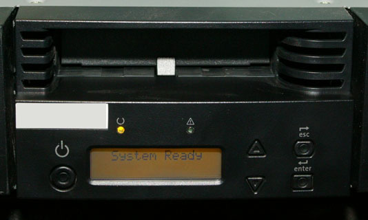
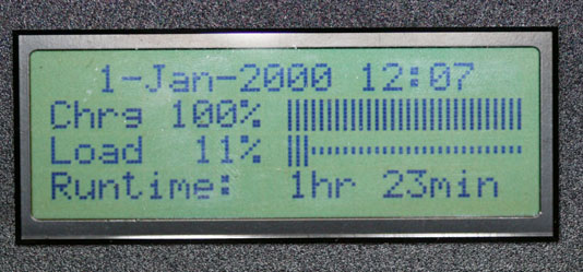
In fact, I never found the BIOS display to say anything other than that it is completely happy with a battery:
BIOS battery menu

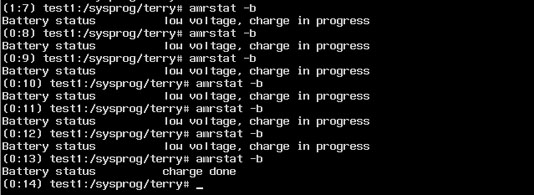
Once I booted the operating system (FreeBSD, in this case) I was able to see more useful data. Each amrstat command was issued about a half hour apart, showing the pack as charging and eventually done:
amrstat report

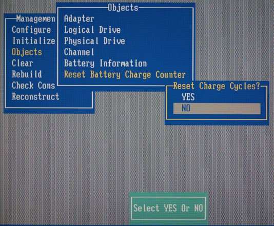
It is probably a good idea to go into the controller’s BIOS setup menu and reset the charge count to zero:
Reset charge count

After letting the battery charge for 12 hours, I removed it and measured the voltage again. The reading of around 4.1 volts is the expected value for a just-charged 3.6 volt battery pack. It will decrease over time, and when it falls below a certain value, the controller will begin charging again:
Voltage of new battery

APC Symmetra RM Front Panel Battery Replacement

I am in the process of restarting an APC Symmetra RM UPS that has been in storage, powered off, for several years. After I installed new batteries in the SYBT2 modules (I had removed them before storing the unit – see my earlier post) – and pro-actively replacing all the fans – see this post, I powered the unit on.

Unfortunately, I was greeted with this rather ominous message:

Panel showing failure message

I didn’t know what “–Failed— Fail!” meant, but it didn’t sound good. Scrolling around in the menus, I discovered that the message was apparently coming from the date/time settings:

Date/time failure message

Both the date and the time were displaying the “Failed” messages and it was not possible to edit either field, the way the date and time is normally set. After swapping out various parts including both Intelligence Modules and the Power Module, I decided to try swapping the front panel with one from a different Symmetra unit. The other front panel displayed the date and time properly, leading me to the conclusion that the problem was in the front panel display module, not the Symmetra itself.

I tried using the front panel “Copy” function on the good front panel to copy all of its settings to the UPS, then swapped back to the bad front panel and did a copy operation to copy from the UPS to the bad front panel. That didn’t solve the problem, so it was time to investigate further.

There are three screws on the back of the cover panel which includes the display panel and the APC logo. Two of them directly hold the display module, while one holds the APC medallion (which needs to be removed to remove the front panel):

Three mounting screws on back

At that point, it was a simple matter to remove the four screws at each corner which keep the two halves of the front panel housing joined, and I removed the front panel circuit board (actually a stack of two boards, one for the display and another with the circuitry):

View of circuit boards

The brownish-yellow rectangular component in the middle of the board is a TIMEKEEPER® SNAPHAT® battery module. This device was designed to “piggyback” on top of a special integrated circuit package, so the battery could be replaced if needed. There are a number of other devices on the market where the battery is not removable, so this is a convenient feature. Here is a close-up of the battery module:

Close-up of battery module

It was a simple matter to carefully remove the battery module, revealing the integrated circuit underneath:

Close-up of socket on IC

I then installed the new battery, and plugged the panel back in to see what it would display. Fortunately, no further work was needed as it immediately showed the default date and time:

Panel is now working

I reassembled the front panel, installed it back in the Symmetra, and set the date and time:

Panel re-installed in Symmetra

It looks like everything is now working perfectly on that Symmetra, and it was much less expensive than purchasing another front panel (the least expensive used one I could find was around $250), as well as keeping components out of the e-waste stream. The replacement battery cost around $5, plus shipping.

If you perform this repair, or even if you just take a close look at your Symmetra front panel, you will want to make sure you’re running the latest firmware for the front panel. APC calls this “Rackmount PowerView” on their web site, and the latest version is 14. The number like .001 after the 14 is the language version (for example, 1 is English and 5 is Spanish). In order to update the panel firmware you’ll need the rather odd Y-cable that came with your Symmetra – it adds a 9-pin serial connector in between the front panel and the intelligence module. Full instructions are on the APC web site.

The Ultimate Studio 1558

Updated March 4th, 2021 to reflect current hardware. You might want to look at my post “The Dell Studio 1558 – Still a nice laptop in 2021” for a more recent perspective, or see a list of all of my Studio 1558 articles here.

A number of people have asked me what changes I made to my 1558 to describe it as “one killer system” (in a comment replying to a poster in the antenna entry). Here’s what I can think of, off the top of my head:

  • Upgrade CPU from Core i5-450M to Core i7-740QM
  • Upgrade memory from 6GB to 16GB (system limit)
  • Upgrade display from glossy 720p to matte 1080p
  • Upgrade keyboard to backlit model
  • Upgrade DVD burner to Blu-ray burner (UJ-235A)
  • Replace lid with one that has all the antennas in “brushed silver” (previously I had a lid which matched the color of my race car, but over the years the matte surface got sticky)
  • Replace palmrest with one that has a topo map pattern instead of the default chainlink (which also includes a new touchpad)
  • Upgrade wireless LAN card to Intel Ultimate-N 6300
  • Install Bluetooth 365 module
  • Install DW5808 mobile broadband / GPS card
  • Replace 320GB HD with 1TB Samsung 860 EVO SSD
  • Upgrade battery from 6-cell to 9-cell (aftermarket as Dell no longer sells replacement batteries for the 1558)
  • Make the power supply more sleek – replace the “hammerhead” power cord with a normal one and remove the rubber strap (I use Velcro cable ties to manage all of my cables)
  • Install Windows 10 LTSC x64 instead of Windows 7 Home Premium x64
  • Use a nice Targus “Unofficial” 16″ slipcase to carry the system

As configured, it gets a Windows 7 Experience Index of 5.7 (yuck!), but that’s due to a poor desktop graphics score from the Mobility Radeon HD 5470. [Of course, the integrated graphics option would probably be a lot worse – if you have a score for that, let me know in the comments.]

Dell Studio 155x 1080p Screen Upgrade

As promised, here’s the article on upgrading your Studio 155x from a 720p screen to a 1080p one.

First, I should caution you that I did this on a Studio 1558 with the ATI Radeon HD 5470 graphics option and a 720p LED panel. I can’t promise that it will work on models other than the 1558, or with the older ATI HD 4750 or built-in Intel graphics. If you have success with any of those, comment here and I’ll add that information.

Some people might ask why I didn’t purchase my 1558 with the 1080p screen in the first place. By the time I was ready to buy the laptop, Dell had cut way back on the available configurations as they were phasing out the Studio line. Also, if you look at used / refurbished 155x systems on eBay, you’ll see that most of them have the 720p screen and that 1080p units cost more (and have less selection) than purchasing a 720p unit and upgrading the screen yourself.

Refer to the service manual (or DCSE if you have it) for detailed disassembly procedures. With some practice, you can do this without dismounting the lid from the base, but for first-timers I’d recommend following the service procedures.

If you have a lid without the wireless broadband or Bluetooth antennas (see earlier post), this would be a good time to change lids since you’re going to have the system apart anyway. A spare bezel (interchangeable parts W440J or 06DV9) may be useful to have, in case you break any of the latch tabs when removing the old one.

Assuming your 1558 has discrete Radeon HD5470 graphics, you will need a W805M cable. Refer to the parts list at the end of this article if your 1558 has integrated graphics. This connects the mainboard to the flat panel, and also includes the cable for the camera. You cannot re-use the W439J cable from your 720p display – it has different wiring. If you purchase a used cable, you will also need some double-sided tape to attach the cable to your new panel. Be careful when purchasing this cable – many eBay sellers think these 2 part numbers are interchangeable – they aren’t. To help you identify a cable in an eBay listing (watch out for “Picture may not be of the actual item” in the description), here are extreme close-up photos of the 2 cables.

This is the W439J cable for a 720p display (LED panel end). Note that there’s a big gap in the middle of the connector with no wires, and a sequence of blue and black (some look white due to the camera flash) wires to the right of the gap:
W439J (720p) cable

This is the W805M cable for a 1080p display (LED panel end). This cable has wires spaced pretty evenly throughout the connector. The sequence of yellow and blue wires indicates that this is for a 1080p panel:
W805M (1080p) cable

You will also need either a H162K (gloss) or C088T (semi-matte) 1080p LED panel. Watch out for “compatible” panels – these 2 part numbers have a display ID (EDID) coded into them, and the notebook won’t accept the display panel if this ID is missing. If purchasing on eBay, you might want to ask the seller for a photograph of the back of the panel, and/or a guarantee of a 100% refund if the panel isn’t compatible.

Here is what the back of the C088T panel looks like:
Back of the 1080p panel

This is a close-up of the label with the Dell part number:
Dell part number sticker

The first thing I suggest doing is plugging your new cable into the new panel and running a few tests. Do NOT stick the tape on the cable to the panel yet. You can lean the new panel up against the lid (in front of the old panel) and plug the cable into the mainboard.

Your first test will be to run a panel power-up diagnostic. To do this, press and hold the “D” key on the keyboard (D for display) while pressing the power button. The display should cycle through a series of solid colors and then go dark. With this test, you’re verifying that you have the cable attached properly and that there are no bad pixels (or an acceptable number, if you purchased a panel with possible pixel defects to save money). A brief flicker before the panel displays the first solid color (white) is normal and not a defect with the panel.

If that test passes, power off the system and then power it back on. You should see the Dell logo and the system should then boot into Windows (or whatever operating system you are running). If you get a black screen and the system appears dead, you have a panel that does not have its EDID programmed (most likely), an incompatible panel, or you have a system that doesn’t support 1080p (not likely, at least if you have the same 1558 with HD 5470 graphics that I do).

At this point, you can shut down the system and commence the panel swap. Set your new panel aside while you remove the old panel from the lid. Be sure to carefully unplug the cable from the camera before pulling the old panel away from the lid. Set the old panel face-down on a padded surface (to prevent scratching it). Place your new panel on the padded surface in the same orientation. You should now see where the sticky tape holds the cable to the old panel (3 places – by the panel’s 40-pin connector, at the edge of the panel where the cable changes to round, and at the edge of the panel where the camera is located). Carefully peel the backing off the new cable’s sticky tape and stick it to the new panel. This will involve pressing (gently!) on two areas of the panel that have “Don’t Touch!” warnings.

Now, remove the mounting brackets from the left and right sides of the old panel (2 screws on each side) and transfer them to the new panel. Left and right are NOT interchangeable, so keep track of what goes where. If you are building a whole new lid, you could use a set of spare brackets, part number W981J. You may need 4 screws to go with the brackets if they aren’t included. You might also want the camera, part number 7RGXF. With all of those parts, you can build a whole new lid and keep the original as a spare.

Carefully re-install the new panel, taking care to plug the webcam cable in before trying to seat the panel all the way. Re-attach the lid to the base of the PC if you removed it. Plug the display and camera cables into the mainboard and boot your operating system to ensure functionality. Be sure to test the webcam as well as the display – you don’t want to have to disassemble the lid once you put the bezel back on. Make sure that the display cable is routed under the tab at the point where it makes a 90-degree turn toward the connector. If the cable isn’t properly located, you’ll get a bulge in the keyboard surround because it won’t seat properly. I’ve observed this on new systems from Dell as well.

If the display and camera are operating correctly, you can now attach the bezel to the lid and replace any other parts that you removed to work on the lid, such as the keyboard surround.

You may find that the default Windows text size is too small when using a 15.6″ 1920 x 1080 display. You can refer to this Microsoft article to select a larger text size. Dell ships their 1080p 155x systems with this set to 125%. Dell also modifies the login screen font size, which requires editing the Windows Registry. You can find an article describing the procedure in Microsoft Answers.

Here are the most common part numbers you will need:

  • 4DKNR – 1558 motherboard with discrete Radeon HD5470 graphics
  • G939P – 1558 motherboard with integrated CPU graphics (no quad-core support, often doesn’t have WWAN connector)
  • 2X6C1 – heatsink/fan assembly for discrete Radeon HD5470 graphics
  • 644D0 – Heatsink for integrated CPU graphics
  • W956J – Fan for integrated CPU graphics
  • W805M – display cable for discrete (1920 x 1080 display only)
  • W439J – display cable for discrete (all except 1920 x 1080 display)
  • NHKMC – display cable for integrated (1920 x 1080 display only)
  • RWH6V – display cable for integrated (all except 1920 x 1080 display)

Converting a system from integrated graphics to discrete Radeon HD5470 graphics will require a 4DKNR motherboard, a 2X6C1 heatsink/fan assembly, and a W805M or W439J display cable, depending on your screen resolution.

Edit: Updated 24-Mar-2021 to fix dead link to Dell service manual and add a section on motherboard and display cable part numbers and upgrading from integrated to discrete graphics.

APC Symmetra RM Fan Replacement

Two years ago I wrote about the second set of replacement batteries for my APC Symmetra RM UPS. Those batteries are still working, but at 8+ years old the various fans in the UPS were getting a bit tired and making various high-pitched whines and grating noises, so it was time for a complete set of replacement fans.

There are 3 different types of fans used in the Symmetra RM – ones in the SYPM2KU power module (2 fans each), ones in the SYTF2 transformer (2 fans each – see footnote), and one in the Symmetra RM chassis itself.

The fans used in the power module are Mechatronics F8025X24B-FHR which is rather hard to find. I purchased mine from Online Components. You will have to splice the connectors from the old fans onto the wires of the replacement fans. If your UPS has sufficient redundancy to allow removal of one power module at a time, you can replace these fans without shutting down the UPS.

The fans used in the transformer are NMB-MAT 3115PS-12T-B30. These are widely available and I purchased mine from Newark Electronics. Note that it is perfectly normal for only one of the two fans to run – the other one is used only when the transformer detects an overheating condition. The cable for these fans just plugs into the fan – no re-wiring is necessary. You will have to shut down the UPS and disconnect the transformer to work on the fans, however.

The main Symmetra RM fan is a Comair-Rotron FE12H0X-039453 which is a semi-custom part for APC. This fan also has a sensor to report its speed, so you can’t just substitute a random 80mm fan. Fortunately, APC makes it possible to order this part at a reasonable price. It is APC part 490-0024B. I ordered mine from CDW, and despite it being a special-order item, it shipped rapidly. This fan comes with the necessary connector pre-installed. It can be replaced while the UPS is running, however the UPS MUST be placed into bypass mode via the switch on the rear panel, or the UPS will shut down with a “System fan fault” error when you unplug the old fan.

The old fans provided nearly 9 years of continuous service, and not all needed replacing – I just decided it would be better to replace them all at once rather than one-at-a-time as they became noisy.

Dell Studio 155x Wireless / Networking Options

Today I’m going to start a discussion regarding the late-model (1555/1557/1558) Dell Studio laptops and their wireless and networking options. This started when I ordered a Dell Wireless 5620 card for a Studio 1558 computer I had purchased. This is the combined mobile broadband / GPS card intended for the Studio 155x systems.

I was quite surprised when I opened the access panel on the bottom of the computer to install the card and discovered that there were no antenna cables for it in there, despite the service manual saying there would be.

As I continued to investigate, I found a number of places where the service manual was flat-out wrong, and a bewildering array of Dell part numbers. Let’s get one thing out of the way – the “Service Manual” that Dell makes available on their web site is NOT the manual that their techs use. Their internal manual has a lot more information and goes into things in a lot more depth than the customer service manual. Dell doesn’t make their internal manual available to the public, but you might have some luck with search terms like “Dell Certified Systems Expert” or “Dell Foundations 2009 Portables”.

Anyway, let’s get the easy stuff out of the way first. That will be Bluetooth. The customer service manual claims that there are 3 mini-PCI Express sockets underneath the bottom cover. That is only true for some systems. On both of my 1558’s there was a soldered-in chip where the manual says the Bluetooth socket is located. I am not sure what that chip is (it is under a heat sink). It isn’t the ATI graphics chip as that is next to the CPU and handled by the main system heat sink and fan:

Mini-PCI Express Sockets

That’s OK, because that card needs an external bluetooth antenna, which your system probably doesn’t have. Fortunately, there is a second Bluetooth socket on the other side of the motherboard. That socket takes a Wireless 365 bluetooth card that doesn’t need an external antenna:

Alternate Bluetooth location

Unfortunately, getting to this location involves a near-complete disassembly of the laptop. For the gruesome details, look at the service manual in the link above.

The first picture in this article shows an Intel Ultimate-N 6300 MIMO (3-antenna) WiFi card and the Wireless 5620 card installed in the card bay. Careful observers may have noticed that the 6300 card doesn’t have a Dell part number on it. That’s because I purchased a generic retail card, not the Dell one, as I could get it for a better price that way. Installing the cards is the easy part. If you didn’t order your computer with the 5620 option, you won’t have the antennas you need. When I asked Dell why they sold a card that couldn’t be used, they just sort of mumbled “dunno”. I don’t understand why they did this – it created a huge assortment of part numbers for them to inventory (aside from making upgrades harder). The Studio 155x was available in at least seven different lid colors. Each of those has at least three possible antenna configurations – WiFi only, WiFi + mobile broadband, and WiFi + mobile broadband + Bluetooth. That creates 21 different part numbers to stock instead of 7 if they built the systems with all the antennas.

Dell won’t sell you a replacement lid (even if you could figure out the correct part number) because it isn’t considered a customer-replacable part. So it is off to eBay, where I discovered that sellers had no idea what options the lids they were selling included. I received flat-out incorrect answers from a number of sellers I’ve found to be reliable in the past.

The next part of this article could be called “A Field Guide to Studio 155x Lids”. It will teach you what to look for in an eBay auction, as well as how to tell if a lid is really new as the seller says. Later on I’ll tell you the part numbers for the most common lid and bezel to help your searches.

This sequence of four photographs shows the four corners of the inside of a Studio 155x lid. I’ll start at the top left and proceed clockwise. This first picture shows you the WiFi antenna. It will have 2 wires, a black and a white, that connect to the WiFi card in the base. This particular antenna also includes one of the mobile broadband antennas which is black with a gray stripe. Note that this is one particular style of lid – others can have silver-colored foil instead of the copper you see here, may have black circuit boards instead of green ones, and may have different markings. The important thing is whether or not there is an antenna at each location, not what it looks like:

Top Left

Next is the antenna at the top right. If your lid has this antenna, it supports mobile broadband. This antenna has one wire, gray with a white stripe:

Top Right

Now we have the bottom right antenna. If your lid has this antenna, it supports Bluetooth. This antenna has one wire, which is blue:

Bottom Right

Last is the bottom left. This is the MIMO (3rd) antenna for WiFi. All lids have this. The antenna has one wire, gray:

Bottom Left

Now that you know how to tell what antennas are included on a lid, I’ll show you how to tell if it is new or used. New lids will have clear plastic caps on all antenna wires (anywhere from 3 to 6, depending on what antennas are installed):

Caps on antenna wires

Caps on antenna wires

If your lid doesn’t have all the caps installed, it is almost certainly a used lid. Next, the antenna wires and the wire from the power switch will be taped near the middle of the lid with masking tape:

Tape on inside of new lid

The outside of a new lid will also have a piece of protective clear plastic on it, with 6 cutouts for 6 pieces of masking tape:

Tape and protective cover on outside of new lid

One thing to be careful of is sellers who mark their listings “Photograph may not be the actual item”, or who list the condition as “New – Other”. I’ve found lots of New – Other listings which were actually parts stripped off of systems.

The part numbers you probably want are W855P (sometimes written 0W855P) and W440J. The W855P part is a lid with every possible antenna installed, in the “Black Chain-link” color (which seems to be the most popular color). The W440J is the black bezel that snaps on the inside of the cover. You’re almost certainly going to damage at least one of the latch tabs on your old bezel when you take the display apart, so you may as well order a new one with the lid and just use that. Part number 06DV9 is an interchangeable part number for the bezel.

If, for some reason, you want the part number for some other combination of color and antenna (like Plum Purple w/ mobile broadband but no Bluetooth), add a comment to this entry and I’ll post it.

The next 155x article will be the highly-anticipated tutorial on replacing a 720p display with the 1080p one.

Edit: Updated 24-Mar-2021 to fix dead link to Dell service manual and provide currect motherboard part number (in comments).

Trans-Siberian Orchestra @ Prudential Center 12/18/10

Just got back from the TSO show in Newark, NJ. I’ll update this post with a more detailed write-up and some video later on, but I wanted to get some of the pictures I took posted right away.

Update: Added a video and some additional text.

My camera (a Fujifilm F300EXR) had a lot of trouble with the lighting at this show (compare with the same camera shooting the Rush concert in the previous blog entry). The problems were due to the stage either being dark or flashing brief bright lights / fireballs. These are some of the best shots:

TSO

TSO

TSO

TSO

TSO

TSO

TSO

TSO

TSO

TSO

To give people in the “cheap seats” a better show, various performers would run to a second stage at the other end of the arena floor, or out on catwalks suspended above the arena floor:
TSO

The finale – there were lots of streamers and sparklers, including pinwheels:
TSO

At the end, various performers gave away items to people in the first dozen or so rows – drumsticks, violin bows, guitar picks, and so forth. One boy was presented with a guitar used in the show.
TSO

Here’s a video I shot of Christmas Eve/Sarajevo 12/24. Sorry about the poor focus and the streaks in the video – the camera was having a very difficult time in the show’s very dim lighting. Hopefully the sound will make up for it:

(The above video is the full 720P version. Click the Icon icon on the top right to go fullscreen.)

Rush – Time Machine Tour @ PNC Bank Arts Center 9/3/10

I just got back from the Rush show at the PNC Bank Arts Center (which most people still call the Garden State Arts Center – that’s from before the state started selling naming rights to everything).

I’ll update this post with lots more details later – it was a great show. In the meantime, I thought I’d put up some of the pictures we took. Photos by me unless noted otherwise.

In keeping with the theme of previous tours, there’s a particular set layout (in the past we’ve had a laundromat and chicken rotisseries). This time the set style was steampunk, with boxes with tubes, dials, steam vents, etc. – one of which was making sausages!
Caption

Although Rush has been touring for 35-odd years (well, the first time I saw them was in 1976), they still seem to be having a genuinely good time. Given how few bands from that era are still touring with their original members*, this is even more amazing.
Caption

Caption
Photo by S. Forte

Alex plays the mandolin. He seemed to be having some trouble with guitars tonight – there were a number of unexpected swaps during the show, and at one point he made hand signals to the stage crew that he couldn’t hear anything in his headphones.
Alex with mandolin
Photo by S. Forte

Here’s part of the animation that played during Moving Pictures.
Moving Pictures workmen
Photo by S. Forte

During Neil’s drum solo, a fanciful animation of a robot playing drums played on the giant video screen.
Video during drum solo
Photo by S. Forte

Caption

At various points in the show, characters came out to tend to the sausage machine and remove sausages, to dust Neil’s drum kit with a feather duster, and so on.
Sausage wagon

As the show progressed, the signs behind Geddy changed from Real Time to Half Time to Bass Time to Sausage Time.
Real Time

Performing is hard work – particularly when you’re a 3-piece and don’t use additional musicians. And these guys are each 57 years old! There are points in the show where Geddy is playing bass, performing keyboards, and singing at the same time. And I know people who can’t walk and chew gum at the same time… Alex was really working up a sweat – by this time, his shirt was soaked through. I counted at least 4 different shirts on him, all of which got soaked.
Alex soaked

Near the end of the break between sets, the clock on the Gefilter started counting up toward the present.
Gefilter clock

Caption

Caption

Caption

Caption

The Starman from 2112.
2112 Starman

Here’s a video I shot of Red Barchetta:

(The above video is the full 720P version. Click the Icon icon on the top right to go fullscreen.)

* Yes, I know about John Rutsey. But he’d left the band before I saw them for the first time.

Dell Bluetooth Keyboard & Mouse on Windows 7

I’m still working on my comprehensive Dell Windows 7 upgrade article, but I have enough information about the Dell “Bluetooth Keyboard & Mouse” bundle that I figured I’d post it now…

Dell had offered a Bluetooth keyboard and mouse in a number of combinations and different part numbers. The particular one I have is Dell Part Number 0YJ101 (YJ101) which includes a USB Bluetooth transceiver. Other versions of this package were targeted at notebooks that had Bluetooth built in, and therefore didn’t include the transceiver. The keyboard part number is DH953 and the mouse is DH956. [I’m including the part numbers here so people searching for those numbers find this article.]

This package was actually made by Logitech for Dell. The Dell driver was last updated nearly 2 years ago, in March of 2008 (Version 3.22, A02-00, here). Looking on the Optiplex 760 page, this package is supported through Windows Vista, but not on Windows 7.

Fortunately, a little searching on the Logitech web site finds the SetPoint software, version 4.80, here. If the link doesn’t work, search for drivers for “Cordless Desktop® LX 300” on Logitech’s web site. Both 32-bit and 64-bit versions of SetPoint are available.

I successfully downloaded and installed the 64-bit version on a fresh Windows 7 Ultimate x64 install. The keyboard and mouse are both recognized as Dell devices and are fully functional. After installation, SetPoint will check regularly for software updates.

The next issue I had (which wasn’t new with the Windows 7 install) was what can best be described as a “drunk mouse” – response to mouse movements would be delayed, and would then wildly overshoot the intended location. I’d had this happen under Windows XP as well, but not as often. After thinking about it for a while, I formed a theory that this was due to radio frequency (RF) interference from the Optiplex 755 chassis. The problem would get much worse when I was running software that stressed my new video card (an ATI Radeon HD5770), such as the Unigine benchmarks. The Bluetooth receiver normally plugs into the USB ports on the back of the case, right next to the video card. I unplugged it and used a 6 foot USB A/A shielded extension cable to relocate the transceiver away from the system unit and the problem seems to have disappeared. It might be possible to avoid the problem by plugging the transceiver into one of the USB ports on the front of the case, but I didn’t want it sticking out where it could get bumped and snap off.

Mike Batt’s Zero Zero (and the Mike Batt Music Cube)

Zero Zero is the title of a Mike Batt album which is the soundtrack to a video production he created for Australian TV in the early 1980’s. If you’ve heard of it, you know exactly what it is. If you haven’t, the one-line summary is “Boy in a future society where emotions have been banished falls in love and gets a lobotomy for his trouble.”

Zero Zero - Main Title

This video has never been officially released. All that has been available has been a YouTube video of one of the songs.

Mike Batt’s official web site entry says “Since opening the Official Mike Batt website, we have received more corespondence (sic) about Zero Zero than any other project.”. At various times, a stand-alone release of Zero Zero was reported to be “coming soon”, and earlier this year, “this Fall”.

While a stand-alone release of Zero Zero still seems to be unavailable, a DVD of the performance has been included in the Mike Batt Music Cube, a compilation of nearly all of Mike’s work (the only albums that appear to be missing are “Classic Blue” and “The Very Best Of”). In his usual humorous way, Mike says: “After 40 years in the industry, this could either be seen as a service to fans or the biggest ego trip on Earth. In fact it is a combination of the two.”

I was lucky enough to get an early shipment of the Music Cube from Amazon UK, when they had it priced at £48.68 + £3.08 shipping to the US (about US $84). The Amazon UK price has since increased to £74.98. If you want to help improve their profits, Amazon US will sell it to you for $207.98 (up $16 from when I first posted this article).

Of course, the first thing I did when I got it was to pop the Zero Zero DVD into the player (article continues below):

Zero Zero - Characters Playing Cards

Zero Zero - Number 17 Emoting

Zero Zero - Brain Surgery

Zero Zero - Dance of the Neurosurgeons

I won’t spoil the surprise for you, but I will say that there is something about Number 36 that you’ll discover when watching the video, even if you’ve listened to the record many times.

Picture quality is quite good for something that’s nearly 28 years old. Judging by some lint on the image, at least part of the project was originated on film and then transferred to video. As is usual with video-to-DVD transfers, there is some slight underscan, so you can see the last interlaced line on the bottom of the image and there is some fuzziness at the left and right edges of the video. This does not detract from the overall appearance, though. The only other video copies I’ve seen have been Nth-generation copies of an off-air taping of the show, and this DVD far exceeds all of them in quality.

The disc is Region 0 (plays on any player regardless of country) but is mastered in PAL, so some NTSC players and televisions may have problems with it. You can always watch it on a PC that has a DVD drive, of course.

Audio is similarly good. And of course the Music Cube includes a remastered version of the CD if you just want to listen to the music.