Article updated 3-Jan-2018 to add information on the SLW clock / RPTR-OLED.
Article updated 6-Feb-2012 to add information on the GEN II clock and to re-organize the presentation.
Each of the images is clickable to display a higher-resolution version.
If you want to discuss anything about this clock, you can do so on my blog.
Information about ordering the clock is available from the BadNixie.com web site. Also, you can read the extensive 102-page manual (by yours truly!) in PDF form here or in HTML form here
I have been an avid collector of Nixie tube clocks for many years now. I also enjoy building them from kits - they're filling up the house as I have several dozen now.
I was very interested when I heard of a new "modular Nixie" kit (also available fully-assembled for a slightly higher price) from H Carl Ott and Michael Barile planned for early 2011 which would use some of the large B-7971 tubes that I'd collected over the years. I had acquired the tubes with plans to use them in a different kit that didn't pan out, so this was a great chance to put them to use.
I ordered one of these kits, now known as the MOD-6_7971, and was amazed at the care with which it was designed and the features that were available. Most of the Nixie clocks I own are set with two or three buttons in a rather non-intuitive manner, or require a USB host system (PC or Mac) to set the time. The MOD-6 accomplishes everything using a single rotary encoder with pushbutton. Of course, it helps that the 6 tubes can display alphanumeric characters as well as digits - but I think a lot of it is due to the excellent design of this clock.
![[Operating GEN V clock]](6f5s9428-s.jpg)
You don't really get an idea of the size of this clock from this picture, but it is big! The clock is over 20" wide and 7" tall. Each digit (just the lit part) is 2½" tall.
This is the current "GEN V" version of the clock with the new-style base and latest CPU version. Most of the "smarts" for new features such as random word display, temperature / humidity / barometric pressure / etc. comes from the GPS repeater, now called the RPTR-OLED (OLED stands for "Organic Light Emitting Diode") to distinguish it from the earlier versions. The OLED display allows arbitrary characters and symbols to be displayed on a crisp, clear background.
In addition to the new-style base, the control knob (formerly on the right side of the case) has been moved to the back to provide a more streamlined look. The cable coming off the right rear of the clock is for the optional PIR (passive infrared) sensor, which is used as a motion detector to turn the tubes off when not in use.
![[Operating GEN II clock]](6F5S8511-s.jpg)
This is the older GEN II version of the clock. It has always been possible to update a clock to a newer generation by upgrading the CPU and adding any new options desired. In fact, the clock shown in the first picture on this page started out in life as a GEN I clock and has been updated whenever a newer generation was released.
After I assembled the kit and discovered what a gem I had found, I asked if I could purchase some additional kits. "Sorry, sold out", I was told. But there might be another batch if there was sufficient interest. So I sat and mostly-patiently waited (I admit that I sent a couple "are we there yet?" messages to the clock's discussion group).
After some time, it was announced that there would be a "GEN II" version of the clock, which would include both GPS time synchronization and a temperature display - and best of all, the GPS receiver was connected to a short-range radio repeater module, so there wouldn't be any of the usual "let's order a bunch of 10-foot PS/2 extension cords and see if we can get the GPS receiver to work 30 feet away from the clock" silliness.
![[The keyfob]](6f5s9488-s.jpg)
One of the features added along the way was a keyfob which can be used to configure all of the clock's options via a convenient remote control.
![[The RPTR-OLED module]](6f5s9567-s.jpg)
This is the latest RPTR-OLED module. The PS/2 GPS connector has been removed, since the module now includes a built-in GPS receiver. The GPS antenna cable is shown exiting the back left of the picture. The antenna on the back center is a "rubber ducky" type antenna for the module to communicate with the clock. The module uses a higher power radio than the older GPS repeater, so an external antenna is required. The clear acrylic cover was removed for this picture in order to provide a clearer view.
The RPTR-OLED module also contains temperature, humidity, and barometric pressure sensors as well as providing words for the clocks "random word" display feature.
![[The radio repeater module]](6F5S8524-s.jpg)
This is the original GPS repeater module which used an external GPS receiver connected via a PS/2 type connection.
![[Temperature display]](6F5S8523-s.jpg)
Here the clock is displaying the room temperature. Note the clever usage of the upper right colon lamp as a degree symbol.
![[Completed GEN I clock]](6F5S8153-s.jpg)
This is the completed clock, without its clear acrylic top installed. It is really a work of art, and I have to compliment the designers for a wonderful product.
The clock uses 5 circuit boards which connect together. From left to right, the boards are:
- Power supply (8 and 180 Volts)
- Tube board (2 tubes) and AM/PM indicator
- Tube board (2 tubes) and colon lamps
- Tube board (2 tubes) and colon lamps
- CPU board (with control knob and light sensor)
![[Clock from the top]](6F5S8156-s.jpg)
Looking down from the top of the clock, you can see the attention to detail in the design - the boards are attached to the base with hex head cap screws and black washers to match the circuit boards.
![[Tube and colon detail]](6F5S8167-s.jpg)
In this picture, you can see one of the B-7971 tubes and the very fancy colon tower with copper tubes and neon lamps. You can't see it in this picture (it is printed on the back of the tube), but the date codes on these tubes show that they were manufactured in 1968, 43 years ago at the time I created this web page.
![[Close-up view of colon]](6F5S8165-s.jpg)
Here's a more detailed view showing the construction of the colon tower and lamps.
![[Power supply]](6F5S8160-s.jpg)
This picture shows the power supply. It produces 8 Volts from a standard 3-terminal regulator, while using a packaged high voltage supply to produce 180 Volts. The gray box on the left side of the circuit board adjusts the high voltage, while the nearby jumper can disable the high voltage supply completely for diagnostic purposes. The neon lamp shows that the high voltage supply is enabled and working.
![[Tube pins]](6F5S8498-s.jpg)
On the GEN II kits, I managed to position the tube pins as instructed. As you can see from the next picture, I didn't get them quite right on my original clock.
![[Tube pins]](6F5S8162-s.jpg)
Here you can see the socket pins that hold the tubes in place. This installation deviates slightly from the kit instructions, which specify that the pins should stick further out of the board. A clarification has been added to the instructions for installing the pins.
![[The GEN I CPU board]](6F5S8158-s.jpg)
This is the original CPU board, which contains all of the control functions for the clock. On this side of the board, you can see the backup battery (to maintain the time and option settings if the power is disconnected) as well as the control knob, phototransistor (for the auto-dimming function) and a status LED. There are also jumpers for various bits of future expansion. Most of the circuitry is on the bottom of the board, out of sight. Since most of that involves hard-to-solder surface mount components, it is probably a good idea that you can't normally see them.
Sharp-eyed viewers who also own this model of clock may note that the writing in the serial number box doesn't match the writing on theirs. That's because the PC board cleaning fluid I used to clean the boards after soldering also removed the serial number. I resisted the urge to make up a "cooler" serial number and simply re-wrote 018 as it was when I received the kit.
![[The GEN II CPU board]](6F5S8486-s.jpg)
The GEN II CPU adds a pre-packaged 2.4GHz radio transceiver module, as well as a mini-DIN connector for plugging the GPS receiver directly into the clock if so desired. The CPU board's precision timekeeping remains as accurate as on the original kit, so it is not necessary to use a GPS receiver if you don't want to.
I put the tape over the battery to keep it from popping out of the socket when shipping the clock to a friend.
The serial numbers are still soluble in the PC board cleaner that I use - this time I created printed serial number labels for my new boards to make them look more professional that my poor handwriting.
![[The GEN V CPU board]](6f5s9578-s.jpg)
This is the latest GEN V CPU board. In addition to the radio module on the GEN II CPU board, it adds a connector for a PIR sensor (motion detector) and relocates the control knob to the rear of the clock for a more streamlined appearance.
![[Side view of the CPU board]](6F5S8163-s.jpg)
In this picture you can see some of the components on the underside of the board. The out-of-focus area to the right is the control knob, which handles all of the configuration options on the clock.
The GEN II clocks were offered with an optional polished (mirror finish) aluminum base instead of the matte finish. I decided to stick with the matte finish as I wasn't sure I wanted people to see my soldering on the underside of the boards reflected back at them.
![[Knob and PIR connector on GEN V CPU board]](6f5s9478-s.jpg)
As mentioned above, the control knob was moved from the right side of the case to the rear to streamline the clock's appearance. The round black connector to the right is for the optional PIR sensor.
![[PIR sensor and cable]](6f5s9517-s.jpg)
The PIR (passive infrared) sensor is used to detect motion in the room and turn off the clock after an adjustable period after no motion is detected. The cable allows the sensor to be located somewhere with a good "view" of the room, in case the clock is in a cabinet, etc.
![[GPS connector on GEN II CPU board]](6F5S8508-s.jpg)
This is the GPS connector on the GEN II CPU board. A GPS receiver can be plugged in here or connected via the radio repeater module.
![[TimeLink receiver]](6f5s9498-s.jpg)
One of the nice things about transmitting GPS time throughout the house with the RPTR-OLED is that I can get rid of the tangle of GPS receivers and extension cords for my various other GPS-capable clocks. This picture shows the TimeLink receiver, which decodes the radio signals from the RPTR-OLED and "pretends" to be a plain old GPS receiver for various 3rd-party clocks.
![[Soldered IC]](6F5S8138-s.jpg)
This is one of the ICs I soldered to the underside of the boards (this particular one is the high voltage driver IC on one of the tube boards). In actual size, this chip is only 3/8" square!
![[Quadruplets]](6F5S8546-s.jpg)
As I mentioned above, back when these kits first came out, I tried to buy a second one and was told they were sold out. I decided to not make the same mistake this time, and ordered 4 of the kits. Here they are, assembled. Note that the tubes are not included with the kits and need to be purchased a few at a time when the price is "reasonable" (see the history section below). This picture was taken in my lab as I was testing the clocks, which is the reason for the clutter of cables.
B-7971 history
The largest "affordable" Nixie tube is the Burroughs B-7971, which was used in an early electronic stock ticker system (though not on the New York Stock Exchange itself - that's a common misconception) called the Ultronic Systems Lectrascan. One of the founders of Ultronic Systems wrote a brief history of his company and the Lectrascan. You can view that article (in PDF format) here. For further information about Ultronic from 1970 to the (relatively) recent past, this PDF describes the subsequent corporate history.This is a picture of one of the complete Lectrascan display units, as well as one of the plug-in circuits with two tubes that were sold as surplus:
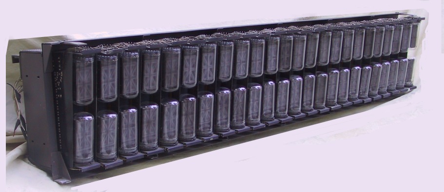
Image courtesy of brian r stuckey - www.ineedcaffeine.com
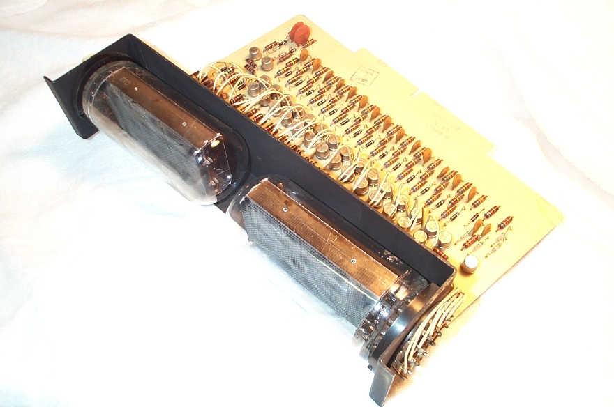
Image courtesy of Robert Schaffrath - www.schaffrath.netAffordable is a relative term - B-7971's routinely sell for over $100 each on eBay. Often those are sold "Untested - as-is", with the buyer assuming all responsibility. Out of 50 or so I've purchased, I've only encountered 2 truly bad ones - one was a complete dud as it had an internal wire vaporized (probably by an unskilled person trying to test it) and one had a single bad segment (which is enough to render it unusable in the clock). Several of the others had weak segments which would not fully light at the dimmer settings available on the MOD-6 clock. I was able to rejuvenate a number of them by "baking" the segments one at a time at a higher-than-normal current. A few of the tubes I'm not 100% happy with and I'll be keeping them as spares.
One tube of the largest known Nixie type, the Rodan CD47, recently sold for over $1,300 on eBay. At that price, a complete 6-digit clock would cost nearly $8,000 just for the tubes - and that's without the electronics or any spare tubes!
Interestingly, in the 70's you could purchase two B-7971 tubes and a circuit board as shown in the above picture for under $5 from electronics surplus shops, like those on Canal Street in New York City, as well as a number of the popular mail-order surplus outlets. That's back when those stock ticker systems were replaced with newer models and the boards were scrapped.
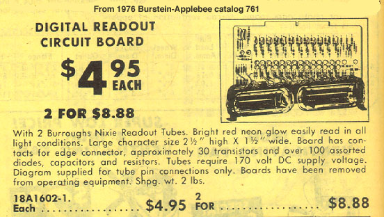
Image courtesy of David Forbes - www.nixiebunny.comBack in early 2006, I purchased a number of B-7971 tubes and ordered some kits from Raymond Weisling to drive the tubes. Unfortunately, Ray never delivered the kits and I was left with a bunch of tubes sitting on a shelf. I didn't think about them much, except for the times I sent Ray an email asking when my kits were going to ship. Eventually those emails started bouncing. The MOD-6_7971 has given my tubes a purpose - and what a fantastic one!
If you're interested in buying your own MOD-6 (either kit or assembled), visit the official web site here.
![[Operating GEN V clock]](6f5s9428-l.jpg)
![[Operating GEN II clock]](6F5S8511-l.jpg)
![[The keyfob]](6f5s9488-l.jpg)
![[The RPTR-OLED module]](6f5s9567-l.jpg)
![[The radio repeater module]](6F5S8524-l.jpg)
![[Temperature display]](6F5S8523-l.jpg)
![[Completed GEN I clock]](6F5S8153-l.jpg)
![[Clock from the top]](6F5S8156-l.jpg)
![[Tube and colon detail]](6F5S8167-l.jpg)
![[Close-up view of colon]](6F5S8165-l.jpg)
![[Power supply]](6F5S8160-l.jpg)
![[Tube pins]](6F5S8498-l.jpg)
![[Tube pins]](6F5S8162-l.jpg)
![[The GEN I CPU board]](6F5S8158-l.jpg)
![[The GEN II CPU board]](6F5S8486-l.jpg)
![[The GEN V CPU board]](6f5s9578-l.jpg)
![[Side view of the CPU board]](6F5S8163-l.jpg)
![[Knob and PIR connector on GEN V CPU board]](6f5s9478-l.jpg)
![[PIR sensor and cable]](6f5s9517-l.jpg)
![[GPS connector on GEN II CPU board]](6F5S8508-l.jpg)
![[TimeLink receiver]](6f5s9498-l.jpg)
![[Soldered IC]](6F5S8138-l.jpg)
![[Quadruplets]](6F5S8546-l.jpg)