Now, I have nothing against most network measurement bots. Most are useful, and the rest are usually well-intentioned, even if they are counterproductive. The one thing these have in common is that they have a page that tells you what they’re doing, why they’re doing it, and who to contact if you have further questions.
There is no contact information provided on the page, there is no statement of how the data is being used (other than that it is “not for sale, rental or release”). The web page source does not contain any useful contact information, either. So they’re collecting this data for their own, unspecified, purposes.
Ok, maybe it is legit, just with a spectacularly bad public relations campaign. Let’s look and see who is behind this:
Ok, so they're hiding behind a privacy service, but seem to be located in Panama. Let's see if the IP address they're using matches:
(0:116) host:~terry# host ipv4scan.com

ipv4scan.com has address 93.174.93.51

ipv4scan.com mail is handled by 5 smtp09.topdns.com.

ipv4scan.com mail is handled by 5 smtp01.topdns.com.

(0:117) host:~terry# jwhois 93.174.93.51

[whois.ripe.net]

% This is the RIPE Database query service.

% The objects are in RPSL format.

%

% The RIPE Database is subject to Terms and Conditions.

% See http://www.ripe.net/db/support/db-terms-conditions.pdf
% Note: this output has been filtered.
% To receive output for a database update, use the "-B" flag.
% Information related to '93.174.93.0 - 93.174.93.255'
% Abuse contact for '93.174.93.0 - 93.174.93.255' is 'admin@ecatel.net'
% This query was served by the RIPE Database Query Service version 1.72 (DBC-WHOIS3)
So, they're using an IP address allocated to Ecatel in the Netherlands. Not exactly close to Panama, is it? Let's see if that address is actually in the Netherlands:
(0:118) host:~terry# traceroute ipv4scan.com

traceroute to ipv4scan.com (93.174.93.51), 64 hops max, 52 byte packets

 [snip]

 8  be2094.ccr21.bos01.atlas.cogentco.com (154.54.30.14)  20.530 ms

    be2097.ccr22.bos01.atlas.cogentco.com (154.54.30.118)  19.664 ms

    be2095.ccr21.bos01.atlas.cogentco.com (154.54.30.38)  20.657 ms

 9  be2387.ccr22.lpl01.atlas.cogentco.com (154.54.44.166)  85.582 ms  85.667 ms

    be2386.ccr21.lpl01.atlas.cogentco.com (154.54.44.162)  85.388 ms

10  be2183.ccr42.ams03.atlas.cogentco.com (154.54.58.70)  95.882 ms

    be2182.ccr41.ams03.atlas.cogentco.com (154.54.77.245)  95.035 ms

    be2183.ccr42.ams03.atlas.cogentco.com (154.54.58.70)  97.517 ms

11  be2311.ccr21.ams04.atlas.cogentco.com (154.54.74.90)  130.510 ms

    be2312.ccr21.ams04.atlas.cogentco.com (154.54.74.94)  94.574 ms

    be2311.ccr21.ams04.atlas.cogentco.com (154.54.74.90)  101.849 ms

12  149.11.38.179 (149.11.38.179)  101.548 ms  118.302 ms  102.141 ms

13  server.anonymous-hosting-service.com (93.174.93.51)  98.234 ms  97.335 ms  96.958 ms
Ok, the server is in Amsterdam, Netherlands. But hiding behind anonymous-hosting-service.com seems suspicious. Let's see where they are:
Well, this is definitely fishy. No legitimate survey would be hiding behind so many levels of indirection.
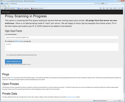
I used the site's form to "opt out" 0.0.0.0/1 with an email address requesting they contact me about their project. I've also sent email to the abuse contacts shown above, pointing them to this blog entry, in the hope that they can get some sort of explanation from their customer.
In the meantime, you may want to fine-tune your firewall rules to prevent this type of probe. That would (at a minimum) include blocking all outside connection attempts on ports 80 (http) and 443 (https) to anything on your network that is not intended to be a public web server. I cannot recommend using their opt-out form as there is no indication of what they do with the information. For all I know, it has the same effect as sending "unsubscribe" in response to a spam email - it just targets you for more spam.
If I receive any information from my inquiries, I'll update this blog entry accordingly.
Updated March 4th, 2021 to change some long-dead links to copies at the Internet Archive Updated July 16th, 2013 to document further idiocy – see the bottom of this post.
Today provided yet another indication that Citibank (and by extension, MasterCard) have absolutely no clue about online security, and past events have shown that they simply don’t care.
As background, I’m sure you remember all the warnings your bank / credit card company gave you about never giving out information to unknown entities, to always make sure that the name of the bank / credit card company is in the URL, and so forth. It sure would be nice if they’d take their own advice…
Today’s experience was triggered by an order on newegg.com. After clicking on the “confirm order” button, I was told that I might be redirected to my bank’s web site to confirm the order. So far so good – I’ve had experiences in the past where every single Newegg order caused my card to be flagged for fraud. But then I was greeted with a web page claiming to be “MasterCard SecureCode”, but with a URL showing “securesuite.net”, which demanded a bunch of sensitive info, including the last 4 digits of my SSN and my billing Zip Code. What the heck? Looks like an obvious phishing site. I let the page sit there while I contacted Citibank MasterCard. The agent said that it was obviously a fake and that I should never enter any info into an online form like that (a statement I strongly agree with). I clicked the “cancel” button and figured that I’d just place my order somewhere else. However, Newegg told me my order had been placed successfully and subsequently sent me an email letting me know that my credit card had been charged.
I then decided to investigate what this “securesuite.net” site was. There aren’t many useful search engine hits, but there is history going back at least seven years, all of which points out the confusing nature of that site. For example:
If you browse to https://www.securesuite.net, you get (as of this writing) a blank page – it doesn’t even return any HTML headers. If by some chance you happen to find https://www.securesuite.net/csi/docs/contact_support.jsp, you’ll find a singularly uninformative page which contains such gems as “Call us at your Financial Institution’s support phone.” To be fair, that may just be a generic template page not intended to be shown to users.
The main point is that after telling us to never trust unknown web sites, the banks and credit card companies are sending people to just those sorts of sites. Talk about mixed messages!
Compounding this, if you do get a call from the Citibank Fraud Department, it will show up as “Unavailable” or “Private” in Caller ID. While it’s true that Caller ID is easily faked, I’d be more inclined to answer the phone if it didn’t look like a random telemarketing call. For added security, that automated call could simply say “This is a fraud warning about your Citi MasterCard ending in 1234. Please call the number on the back of your card immediately.”
This is not a new problem – I’ve been reporting Citibank’s own email to their anti-phishing department becase my mail server (correctly) flags it as fraudulent due to forged headers. In particular, they like to send out email with the subject “Important information regarding your statement”. It is actually just a canned solicitation to switch to online billing, not “Important information”. But Citibank doesn’t send it themselves – instead, they use companies called bigfootinteractive.com and epsiloninteractive.com. As I said in my unacknowledged complaints to Citibank, “Imagine you got an email claiming to be from the IRS entitled “Important information about your tax return”, where the email was sent from a Yahoo account through a GMail account to you. Wouldn’t you be suspicious? You’re doing the exact same thing with the mail you send out.”
These companies should require the use of their own domains and SSL certificates rather than apparently-unassociated third parties, or at least correct information when users call them and ask if the third-party site is legitimate.
It’s a sad day when I have to admit that PayPal does a much better job with this sort of thing than Citibank does.
This total disregard for security isn’t just in their online communications, either. Citibank started sending me unsolicited “balance transfer” checks in the mail again, despite my having gotten them to stop some years ago. I had to call yet again and have my account flagged to not receive them. I said to the phone rep “Who in this day and age thinks sending blank checks in the mail is a good idea?” and she agreed with me. She apparently gets lots of calls about this.
Update as of July 16th:
As I wrote yesterday, I canceled the “MasterCard SecureCode” window and Newegg apparently processed my order, notifying me that they’d received the order and later that it had been successfully charged to my credit card. That’s where things were at the time I wrote the above post.
Last night I received email from Newegg telling me that my order had shipped and tracking information was available, and that I could expect to receive the order on the 17th. That’s excellent service, considering that I had used the “free 4-5 day shipping” option. I figured everything was all set. Little did I know…
Today at 6:37 PM (note that this is at least 12 hours after my Newegg order shipped – talk about “locking the barn door…”) I get the usual “Unavailable” Caller ID phone call from the Citibank Fraud “Early” Warning Department, telling me that my card has been frozen and asking me to confirm that my Newegg purchase was legitimate (oddly, they had no problem with my Amazon purchase later that same day). I told the agent it was, and explained that I’d received the phony-looking SecureCode page and after contacting the same department she was calling me from, who told me it was bogus and to never provide information on that sort of suspicious page, I clicked “cancel”.
The agent proceeded to tell me how important the SecureCode was. She was unable or unwilling (perhaps due to the “script” they’re required to work from) to understand that her department was the one who told me to never provide that information. We went around in circles for about 10 minutes as I tried to get her to understand that, and also to get the point across that they are the ones who say to never provide information to an untrusted 3rd party.
It’s easy enough to dismiss this as “somebody else’s problem”, but the banks, card companies and merchants are covering the losses they incur due to their own stupidity by charging everybody a little more. So it’s everybody’s problem – I just wish the bank could see that it is a problem entirely of their own making.
Carl and Michael recently released the latest version of their MOD-6_7971 Nixie clock. This is pretty much the same hardware as before, but uses a higher-powered radio transmitter in the remote GPS receiver so it can be located further from the clock. There have been a huge number of software changes, however. To give you an idea, the version that shipped with the last batch of clocks was V07-09. The version on this batch is V07-53!
A lot of that was me pestering Carl for changes, but there’s also a lot of other neat new stuff in there.
One other new thing is that the clock now has a 67 page user manual written by me. If I may be permitted to brag a little bit (Ok, a lot!) I think this sets a new standard for Nixie clock documentation. You can read it (and the accompanying updating instructions – you can update any of the older clocks to this software) here:
As my long-time readers know, I don’t make my views on politics, religion, etc. known. That’s because I’ve seen too many message boards (and friendships) torn apart by disagreements between people with different points of view. However, recent events compel me to speak up. As long as the comments remain civil, I’ll leave comments enabled on this post. If things get out of control, I may lock this post temporarily or permanently, or delete the whole thing. With that out of the way…
“They that can give up essential liberty to obtain a little temporary safety deserve neither liberty nor safety.” – Benjamin Franklin
I’m stunned by the revelation that the NSA is continuing to monitor all phone calls, collecting and storing for an indefinite length of time the phone numbers of both parties, the locations of both parties, and the starting time and length of each phone call. [Reference].
Even more troubling is President Obama’s statement that “In the abstract, you can complain about Big Brother or how this is a potential program run amok, but when you actually look at the details, then I think we’ve struck the right balance.” [Reference]
Apparently Congress was informed of this and yet not a single member appears to have raised any objection.
On the heels of that revelation, further information was published showing that a different data collection operation is in progress, sending everything from email to photos to VoIP phone calls, etc. to the NSA. [Reference]
Next, it was revealed that the NSA is also receiving details of credit card transactions. [Reference]
President Obama, I voted for you (twice!) because you campaigned on a platform saying you were different from President Bush and would repeal the “surveillance state” legislation passed as a knee-jerk reaction to 9/11. Not to mention your promise to “Close Guantanamo Bay”. Instead, this is what we get? You make me ashamed to be an American.
“People should not be afraid of their governments. Governments should be afraid of their people.” – V, “V for Vendetta”
I purchase a good deal of used electronic equipment for both work and personal use. Some of that equipment comes from eBay, some is purchased from companies who sell used equipment for a living. The two aren’t mutually exclusive, of course – there are a number of commercial vendors who sell through eBay as well as their own site.
Used equipment can represent a sizable savings over new, particularly when a manufacturer only has a “list price” and doesn’t offer discounts to any but their largest customers. Of course, you need to consider the cost of any required re-licensing (for example, on Cisco gear) when comparing the used price with new. But a large number of manufacturers make updates available for free to all, and in that cases you can often save a great deal of money. Most used equipment will come with at least a one-week warranty against being defective, but some sellers will offer a longer warranty – up to 1 year is common.
One of the best times for great deals is just as a device is no longer being sold as new by the manufacturer. There’s a further drop once the manufacturer no longer supports it with software updates, spare parts, and so on – but you probably don’t want to buy something that far along unless you plan to use it for spare parts yourself.
That’s the benefit to the buyer. But I’d now like to give some advice to sellers, both to ensure the largest market for their items and to avoid potential problems.
Getting the item ready for sale
If the device has any configuration data, erase it before listing the device for sale.
Some devices have no way of resetting them to the default state unless the existing password is given, which means that if the seller doesn’t erase it before selling, the only way a buyer will be able to use it is if the seller is willing to tell them what the password is (not practical if it is the same password the seller is using on equipment they’re still using, or if they don’t know it). Otherwise, the device has to go back to the seller and the transaction voided.
Some other devices have a “reset the password only” option, or (insecurely) a “backdoor” password that works on all units. If the user does that, they will have access to the entire configuration of the device as the seller last used it – at a minimum, things like IP addresses, SNMP communities, and so on. Potentially even more sensitive information like access lists can be disclosed. Additionally, at least two major brands of devices have the (undocumented, but widely known) ability to read or decrypt the original password cleartext once a password recovery procedure is performed.
This is particularly important for disk drives and other storage media. Even if the drives were part of a RAID set, it might still be possible to recover chunks of data from individual drives. You can use a utility such as DBAN to erase drives that are still in the system. It offers a variety of erasure options, from a simple “write zeros to the whole drive” to multiple erase passes with random data. Note that even with this type of erasure, it may still be possible to recover data from certain areas of the disk (replaced defective sectors, for example). If you (or your company) doesn’t want to take the risk, you can remove the drives – but read on for a suggestion about disk trays and mounting hardware.
If you’re selling something like a server and your company policy requires removal of the drives before the sale, put the empty hot-swap drive trays back in the server instead of trashing them with the drives. If the trays require oddball hardware to hold the drives in, put the screws in a small plastic bag and tape them securely to the disk tray(s). The buyer will thank you as they won’t have to scavenge for drive trays to get the server running with new drives.
Unless you’re explicitly selling the item “as-is” or “non-working”, please test it before listing it. Having a 14-day (or longer) “no questions asked” return policy is nice, but neither the buyer nor you want to deal with shipping defective items back and forth. For some items, this can simply be installing (or leaving) them in a system and seeing if they work. Mechanical items like disk drives need some additional testing. Modern drives (anything in the last decade or so) have S.M.A.R.T. testing built in, so it is a simple matter to use something like smartmontools to test the drive and see if it has any problems before listing it. Just today I received a pair of SAS drives, each with less than 30 power-on hours on them, which had over 50 media errors each and had been logging S.M.A.R.T. errors since new (the first failure was logged at 0 power-on hours).
Along with the above, it would be helpful to update the device to the latest available firmware “while you’re in there”, if that is something the manufacturer allows. I’ve received devices that were so old that several intermediate firmware updates were needed to get them to the current revision. In a number of those cases, the intermediate updates were themselves so old that the manufacturer had removed them from their web site as obsolete. That requires the user to go on a “scavenger hunt” through potentially untrustworthy sites to try to find firmware. Another reason to update before selling is that in some cases, the update procedure will only work in the specific brand of equipment the device came from. An example is Dell network cards – the Dell Server Update Utility only runs on Dell-branded servers. Dell network cards are mostly-generic Broadcom, Intel, etc. cards but often have Dell listed in the PCI Vendor ID on the card. This means that generic firmware updates from the manufacturer may fail to recognize the card. To continue my example, even if the user is putting the card in a Dell server, unless Dell offered the specific option card for the user’s server, the appropriate Server Update Utility may not detect / update it.
Listing the item for sale
Be as descriptive as possible when listing the item. To give a specific example of why this is a problem, look for “PowerEdge R300” on eBay. That model was available with or without hot-swap drives and with or without redundant power supplies. It is not possible to convert a chassis from any of those configurations to another. Many times a seller will just say something like “PowerEdge R300 Quad-core 2.33GHz 4GB 2x 146GB HDD”. That doesn’t convey much useful information – in addition to the chassis type, it would be useful to know the exact CPU model, whether the disks are SATA or SAS and if there’s an add-on disk controller in the system, and whether or not there’s a remote access card. This is made even worse by the sellers that say “Stock photo” or “Photo may not represent actual item”. To add insult to injury, some of those same sellers will say “if it isn’t in the picture, it isn’t included” in the body of the listing. Dell’s web site is pretty good – if you know the “service tag” of a system, Dell’s site will show you the configuration as it shipped from Dell. Of course, the seller or a previous owner may have added, removed, or modified components, so don’t take the Dell list as the last word. As the seller, you can go to the Dell site and copy/paste the configuration into your sale listing once you verify that it’s accurate.
If you’re selling something that isn’t an add-on component (like a network card or a disk drive), but can function as a standalone device (like a server, Ethernet switch or network-controlled outlet strip), provide all of the necessary accessories with it or explain clearly that they’re missing. This definitely includes rack mount ears/rails (if the device is rack mountable) and console cables (no two vendors do exactly the same thing once you get to anything newer than 9-pin serial connectors). If the device has cable-management hardware (bracket, etc.) and you have it, include that with the item. Likewise for the faceplate. It is also thoughtful to include the required power cord, at least if the seller and the buyer use the same type of electrical outlets. This isn’t vital, as there are a small number of possible mating power cords for modern equipment. But the buyer will usually appreciate your thoughfulness, particularly if it is an unsual cord like an IEC C20 and they have to order one once they receive your shipment.
Shipping the item to the buyer
Pack the item well, preferably using the original manufacturer packaging (if still available). You’d be amazed at the way some stuff arrives here. I’ve received memory DIMMs ratlling around loose inside a cardboard box. I’ve received servers where parts of the chassis were dented or damaged (usually parts that protrude beyond the basic rectangular shape, but sometimes the main chassis itself). I’ve received devices with glass faceplates that were smashed. I’ve received boxes where the cardboard was too thin for the weight of the item and has ripped during normal handling, with accessories falling out of the box and being lost in transit.
I’d like to be able to say “just take the item to your nearest parcel store and have them pack and ship it”, but that’s generally not a good idea. It seems that their solution for shipping anything is a thin-wall cardboard box and packing peanuts. Those peanuts are not acceptable for anything that might shift around or settle in the box. With enough practice, it is possible to ship fragile items using common materials – I have purchased many items from ex-Soviet countries where the contents were packaged entirely (but carefully) in newspaper and placed in a cardboard box and which arrived here in perfect condition despite their international travel and the rough handling of various foreign postal services.
Large items are generally either heavy or are light enough that they get charged “dimensional weight”, where the shipping company charges the package as if it weighs a certain amount per cubic inch. In general, the cost of reasonable insurance (value up to some hundreds of dollars) will be a small part of the total shipping cost, so it makes sense to insure the package. If you have to file a claim, be aware that you will often be asked to provide proof of adequate packaging before the shipping company will process the claim. I know of one company that took pictures of each box while it was being packaged and retained those pictures, both to deal with shipping damage claims and to prove that a certain item was in the box when it was shipped.
Conclusion
If, as a seller, you follow these steps I think you will find that your items will sell faster and your customers will be happier. And if I’m the customer, I’ll definitely be happier.
Dell has generally been quite good about making firmware updates available in a variety of formats. In addition to the normal Windows and Linux versions, most patches are also available as a floppy / USB image or an ISO image (depending on size). Those of us who don’t run one of the operating systems Dell provides support for appreciate them going through the trouble.
However, newer updates for older systems and updates for newer systems seem to no longer provide standalone installers. In theory, Dell provides a quarterly packaged roll-up of all available updates on a pair of DVD images (CDU and SUU). Booting these and wasting about 10 minutes switching discs should get your system updated to the latest versions of all firmware without any additional steps.
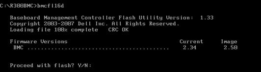
Unfortunately, the firmware for the R300’s ESM / BMC has not been on any SUU discs I’ve looked at, and the update is listed as “Critical Security Update” on Dell’s site (look under ESM on the R300’s downloads and drivers page). The only two formats it is available in are “Windows Update Package” and “Linux Update Package”. I figure that’s not a problem, as I can boot a Windows 7 recovery disk and then run the ESM update from a USB drive. Unfortunately, that doesn’t work. You get an error about “unsupported operating system”.
Next, I boot the CDU DVD and select F3 for Advanced Options. This eventually gets me to a Linux shell prompt (CDU/SUU operates under Linux). I mount the USB drive and execute the Linux version of the ESM update. That errors out with “Not compatible with your system configuration” for some unknown reason. Time to investigate further…
Clicking on “Previous Versions” on the Dell page shows the previous version as 2.46 from 2009. Looking at the available formats, one is listed as “Hard-Drive”. Depending on the mood Dell is in when they create the kit, this could be anything from a freestanding binary that writes a floppy image to a drive, to creating an ISO file, or something that just unpacks into a bunch of loose files somewhere, perhaps then trying to run them (incorrectly) on the local system.
I downloaded that file (link here) and discovered it created 3 useful files when it was executed:
bmcfl16d.exe – a DOS-based flash utility
bmccfg.def – some sort of configuration file
bmcflsh.dat – the actual firmware to be flashed
Now all I needed to do was to find newer versions of the last 2 files inside either the Linux or Windows installer. The Linux installer was a pain, and I quickly gave up on it. I had much better luck with the Windows version (link here). Despite being an EXE file, I was able to use WinZip 16.5 to open the file (browse to the directory where you downloaded the Dell update, then make sure you’ve selected “All files (*.*)” in WinZip’s Open Archive dialog). There’s a whole load of un-needed stuff in there (which doesn’t completely explain how a 655KB update turns into a 4800KB Windows binary). Find the bmccfg.def and bmcflsh.dat files and extract them on top of (replacing) the ones from unpacking the older download.
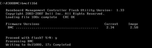
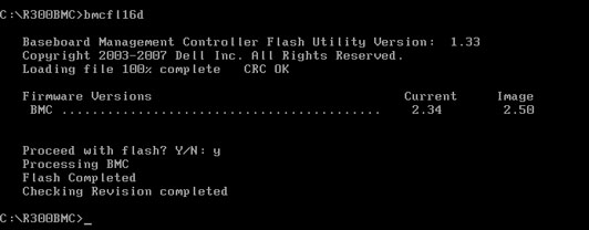
I copied the 3 files onto a bootable USB stick and then used that to boot the R300 to be updated. Here are some screnshots of the various stages of the procedure (it’s very simple – just answer Y or N when asked if you want to perform the update):
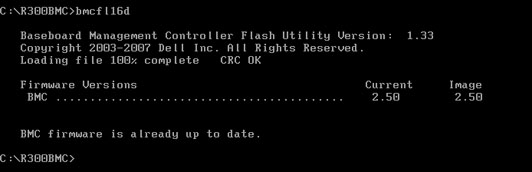
If the firmware is already at the latest revision, the utility will tell you that and exit. This can also be used to double-check that the update was successful:
That’s all there is to it. If you want a pre-built .ZIP file with the flash utility and the 2.50 image, I have placed one here for your convenience.
Advanced topics
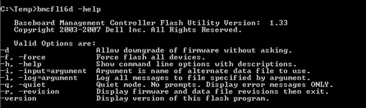
The bmcfl16d.exe utility has a number of documented and undocumented additional features. You can use the -help option to get a list of the documented features. Before using one of these features when updating a system, be sure you know what you’re doing and have a fallback plan in case the update fails and you’re left with a non-operable system.
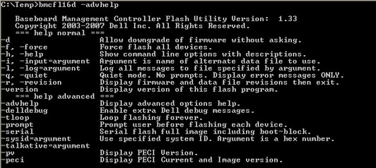
There is also an undocumented -advhelp (advanced help) option, which shows the additional undocumented options:
The above caution about knowing what you’re doing and having a fallback plan is doubly important if you try using any of the advanced options.
Four years ago, I wrote about replacing the batteries in each of the UPS systems I had here. After nearly 4 years, the batteries were near the end of their useful life, and the week-long power outage after Hurricane Sandy (and the follow-on outages once the power finally came back on) finished them off.
I contacted Batteryspec / Tempest (who I’d used for the last big order, as well as for some smaller orders since then) to get current pricing and shipping info. They were back-ordered on the battery type that the Symmetra uses, and shipping costs (which they have no control over) had increased quite a bit since my last big order.
While I’ve been very pleased with Tempest’s product and service, I figured it couldn’t hurt to shop around, particularly as I was looking at a several-week delay before Tempest had their units back in stock. One of the replies to my original post was from Ken Kostecki, whose company carries the Enersys line of batteries. I decided to send him an email message with the list of batteries I was looking for, asking for pricing and shipping costs. He responded right away and gave me good pricing on the batteries and a much lower freight cost – understandable, since the batteries would be coming from less than 1000 miles away, instead of 3000 miles away. At this weight (1500+ pounds), UPS is out of the question – this type of shipment is normally done with a “Less than truckload” (LTL) shipper. He also confirmed that the date codes on the batteries were recent, and even offered to unpack and charge them for me if I wanted. I said that it wasn’t important as long as the batteries were fresh.
After explaining to Ken that I lived on a narrow side street, didn’t have a loading dock and needed a day’s notice so I’d be home, he confirmed that the shipping quote was still good. [In the past, I’ve had experiences where the shipping company didn’t call first and showed up when nobody was home, then charged a $200 “re-delivery fee” – that can clobber any cost savings that the order started out with. I’ve also had 53′ trailers pull up on the next major street over and tell me to come unload their truck, which didn’t have a lift gate. Carrying 1500 lbs of batteries a block and a half is not my idea of fun. Hence wanting to make sure that everything was all set for curbside delivery.]
Within a few days, the batteries arrived in perfect condition, boxed and wrapped on a pair of pallets. I loaded them into the house and began the process of installing them in the various UPS systems – quite a task, as there were around 160 batteries of various sizes, ranging from the small ones used in the Symmetra to car-battery-sized ones used in the Matrix 5000.
As I replaced the batteries in each UPS, I checked the battery float voltage. Incorrect voltage is the thing that will kill batteries the fastest – if the UPS thinks the batteries need to be “topped up”, it will continuously pump power into the batteries, causing them to overheat and eventually swell and burst. APC units (particularly the smaller ones) seem to drift out of adjustment over time, almost invariably in the direction of overcharging the batteries. The Symmetra and Matrix units were fine. The smaller Smart-UPS units I have (700VA to 3000VA) were all out-of-spec by varying amounts. I had to disassemble a pair of SU1000 units in order to get the batteries out, as they had swelled up so much that they couldn’t be removed without disassembling the battery compartment. I don’t consider this to be a problem with the previous Tempest batteries – it is definitely because the UPS’s cooked them.
I followed the unofficial procedure described here to adjust the float voltage on each UPS to the low side of the acceptable range, since I figure that any future aging will continue to shift toward the high side. After bench-testing each UPS for a few days, I placed them back into service. One of the SU1000’s decided it didn’t want to work properly when hooked up to its load (a Dell mini-tower system). After studying it for some time, I decided I’d be better off simply replacing it, rather than trying to find out what was wrong. Fortunately, there are usually a large number of similar units on eBay, often with a “needs batteries” or “does not include batteries” disclaimer – which was perfect as I had a set of brand new batteries. I located a nice SUA1000 (without batteries) for $85 with free shipping. It had a late 2008 date code, which was perfect – units older than that tend to start developing problems, while newer ones have better charging circuitry but are designed to keep manufacturing costs down. After it arrived, I put the new batteries in it, checked the float voltage, and placed it into service. I now had 8 good UPS systems with new batteries.
One of the things I did was to add 2 more “XR” battery packs to my “life support” UPS. This is the unit that provides power to a pair of electric space heaters (for emergency use only), my stereo / TV, cell phone and other battery chargers, and so forth. It will now power all of that stuff for a little over 2 days (vs. 1 day previously), or even longer if I shut down some of the devices it powers. In the past, I’d never had a power failure lasting more than 24 hours, but the electric utility has proven that they’re woefully unprepared for major disasters.
Back on the subject of the batteries – I’ve been very pleased with the service I received from Ken at Engineered Power Systems – give him a call / email if you’re looking for batteries at a good price with great service:
If you’ve been shipped as many Elektronikas as I have, from a variety of countries with very different ideas of what due care for postal parcels means, you’ll eventually encounter something disheartening like this:
You may have purchased a clock where a previous owner changed the faceplate to plastic or glass without the masking areas, or there is extensive damage to the silkscreen on either side of the glass. Or, you might be displaying the clock somewhere you don’t want random people tapping on the glass and possibly breaking it.
In any of these situations, you’re going to need a replacement faceplate. Unfortunately, it isn’t a simple matter of ordering one online from the factory – they haven’t made these clocks for many years, and any replacement glass is likely to encounter the same unkind treatment from the international postal services that got you into this mess in the first place.
Fortunately, I have created a solution for this – replacement acrylic faceplates which are nearly indistinguishable* from the original. I start with precision-cut pieces of colored acrylic (plastic). The pieces I use are cut from 1/8″ (nominal) thick sheets, the same as the original glass. There are four possible choices for color if you’re trying to match the original glass, two of which are much better than the others:
3030 “Glass green” – this is a color designed to mimic real sheet glass. It has a very minimal green tint, just enough to give the edges the green color that real glass has. We don’t care about the edges as they’ll be inside the frame. This is the ideal material for replacing clear glass faceplates.
2111 “Light green” – this color appears to be lighter than the original green glass faceplate, but when installed in the clock, provides a very good approximation of the original green glass color.
2092 “Dark green” – this color is not recommended. While it seems to be the closest match to the original green glass when comparing materials side-by-side on a white background, it imparts much more of a green tint to the tubes and decreases the brightness substantially.
“Clear” – this is also not recommended. It looks quite a bit different from real glass. 3030 is a better choice when replacing clear glass faceplates.
Note that these color codes are the ones used by Altuglas International for their registered trademark Plexiglas® product. Other manufacturers also offer acrylic sheet plastic and generally use the same color codes as a common point of reference. Those colors may differ subtly from the reference Altuglas colors.
If you’re trying to change the appearance of the clock, you’re still limited to colors in the green to blue range. Since those are the colors given off by the VFD tubes in the clock, you can’t do something like using a sheet of red plastic – there’s no red light available to pass through the plastic. Unless you have one of the very rare version of this clock which uses orange MTX-90 tubes, of course.
On the original glass faceplates, lacquer paint was applied to the glass via silkscreen. That’s certainly the fastest and most accurate method for mass production, but would require a lot of prep work for making a few replicas. Instead, after carefully cleaning the acrylic, I applied masks cut from 3M 2060 green painter’s tape, in the shapes of the 4 clock digits plus the colon indicator. Remember, the paint goes on the inside of the glass, so the pattern is reversed from the normal view:
If you are making one of these replicas yourself, this would be a good time to check your mask by sliding the plastic into your clock and making sure that the mask lines up properly with all of your tubes. Even small measuring errors will be magnified as you repeat the masking process across the plastic. After removing the plastic from the test fitting, make sure that it didn’t pick up any contaminants on the masked side – if it did, they will ruin the completed paint job.
Next, I masked off the back side (which will become the front / outside of the completed faceplate). You may be wondering why I didn’t simply leave the protective paper in place that comes on the sheets – that’s because I needed to see through the plastic in order to properly position the mask pattern. I applied 5 thin coats of Valspar 68100 gloss black spray paint, which is a special paint designed to adhere to plastic. One spray can will be sufficient to paint 3 replica faceplates. I alternated painting lengthwise and across the faceplate, waiting 10 minutes between coats. After the last coat was applied, I let the paint dry for 2 hours:
I removed the tape that covered the unpainted side of the panel and carefully inspected the paint for any flaws:
This particular faceplate is for a newer 11-tube clock, as shown by the wider border below the digits and colon. The 12-tube clock has approximately equal border widths, top and bottom.
I then proceeded to carefully peel off the painted masking tape to expose the clear areas of the faceplate:
Here’s a closeup of the painted side showing the finished paint job:
After leaving the paint to fully dry for two days, I prepared to install the vinyl decals that I had custom-cut for the project:
After carefully applying the decals, I had completed replicas, ready to use. From bottom to top:
Original clear glass 12-tube faceplate
Replica 12-tube faceplate in 3030 plastic
Replica 11-tube faceplate in 2111 plastic
These are certainly good enough to look original until examined very closely. See the footnote below for ways to detect replicas.
Here is a picture of the 11-tube 2111 replica installed on the clock with the broken glass shown at the top of this article:
* I have intentionally made it easy to detect a replica versus an original, to prevent people from passing off the replica as an original piece. There are a number of clues, some of which I’m keeping confidential. However, I am documenting three of them here:
The “Э” in Электроника is very circular and doesn’t appear to be italic in the original, while my replicas use a more oval shape with an obvious italic tilt to the letter.
The digit “7” in the original has constant line width and only uses straight lines, while my replicas use a slightly curved shape of varying width.
If you tap gently on the faceplate with your fingernail, a replica will make sort of a dull “plonk” sound as the plastic is more flexible than glass. A genuine faceplate will make a sharp “tink” sound.
In a previous post, I covered the small (relatively speaking) Elektronika 7-06M clock. At the other end of the scale is today’s topic, the Elektronika 7-06 and 7-06K. For background info, consult my prior article as I won’t be repeating duplicate info here.
The operation manual says that the 7-06K version includes a radio correction board not included on the 7-06, and that this is the only difference between the 2 versions. All of the big Elektronika clocks I have in my collection include the radio correction board, regardless of whether the label on the back of the clock shows the model as 7-06 or 7-06K. For convenience, I’ll refer to both of these models as “7-06″ here, except when I need to distinguish between them.
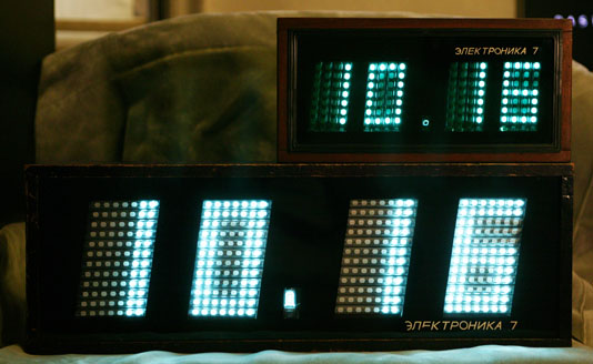
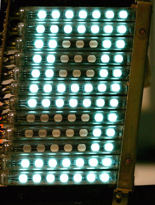
The 7-06 is nearly twice as large as the 7-06M. It is 27″ wide x 9.5″ high x 3.75″ deep. The individual digits are 3″ wide x 6” high. It completely dominates any room it is in, both by its size and by the brightness of the display. Even clock collectors who feel that “bigger is always better” might be intimidated by this clock’s imposing presence. The Elektronika 7-06 digits are both taller and wider than the largest CD-47 Nixie tube.
To give you an idea just how large the display is, the clock’s operation manual says that the time is legible from a distance of 75 meters (about 250 feet). That’s before any fading of the display (and may be somewhat optimistic) but I would have no difficulty believing this clock could be read from 100 feet away.
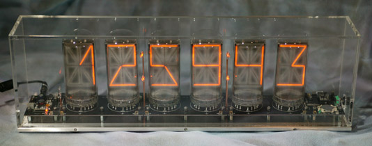
Here is the smaller Elektronika 7-06M sitting on top of the 7-06. Both have new tubes and are running at high brightness (dim mode turned off on the 7-06M, not adjustable on the 7-06). The difference in brightness and dot color is due to the green glass on the 7-06M vs. the clear glass on the 7-06.
Here’s a video of the clock during the transition from 23:59 to 00:00. Being a Soviet clock, it only displays in 24 hour mode.
(Click the icon on the top right to go fullscreen.)
This particular clock bears a label showing the model as “ЭЛЕКТРОНИКА-7” with a date code of “06.1984”. The 06 definitely indicates June, as another clock in my collection has the same abbreviated model number and a date code of “01.1984”. The following picture was taken after I completed my restoration of the clock, replacing the power cord and hardware (screws, bumpers).
There is also a variant of this clock which uses 11 tubes per digit instead of the 12 tubes used in this clock. This introduces an asymmetry in the displayed digits, as there are 2 dark rows of dots on the upper part of the “8”, but 3 dark rows on the bottom part. This seems to have been done on newer production – I have two 12-tube clocks from 1983 and 1984 and an 11-tube one from 1989. The 1983 manual (available below) only describes the 12-tube version, while a newer manual from 1990 only shows the 11-tube version. The 11-tube version seems to have other cost-saving measures as well, such as a lighter internal frame. The case dimensions are exactly the same as the 12-tube version. The paint mask on the inside of the glass is slightly different, as it only exposes the area used by the 11 tubes.
The battery compartment holds 6 Type 373 (D equivalent) batteries for timekeeping during power outages. While the clock will keep time without external power, the display will not illuminate.
The mounting of the electronics / display frame in the case is done in an unusual manner. Unlike the smaller 7-06M where the frame simply comes out the back of the case after removing 4 screws, the 7-06 was initially quite puzzling. After removing the screws that attached the 2 metal back plates and the phenolic battery compartment cover to the case, I could see the circuitry of the clock on the back of the frame, but it wasn’t obvious how to get the frame out of the case. The battery compartment is made of wood and is part of the clock case, so it was obvious the frame couldn’t come out through the back.
However, the front glass was fitted into a recessed groove that ran completely around the case, so there was no apparent method to remove the glass. Operating on the “when in doubt, remove more screws” theory, I unscrewed the 4 screws that held the control panel onto the the left side of the case. These screws were much longer than expected, and when they had all been removed, the control panel could be pulled away from the case. The side panel of the case came along with it, revealing another side panel beneath it. This second panel was fully slotted, so the glass could then be removed by sliding it out to the left.
Unlike the smaller 7-06M clock, the glass on this clock is clear. The black lacquer mask around the display areas has the same construction as the smaller clock, and the ЭЛЕКТРОНИКА lettering on the front is applied in the same manner, though enlarged from the size used on the 7-06M. The clear glass provides a much brighter display than the green glass of the 7-06M, although it does make it easier to see the un-lit dots of the tubes. This was probably done to make the display readable from longer distances. A newer 11-tube 7-06K in my collection has green glass, while both 12-tube clocks have clear glass.
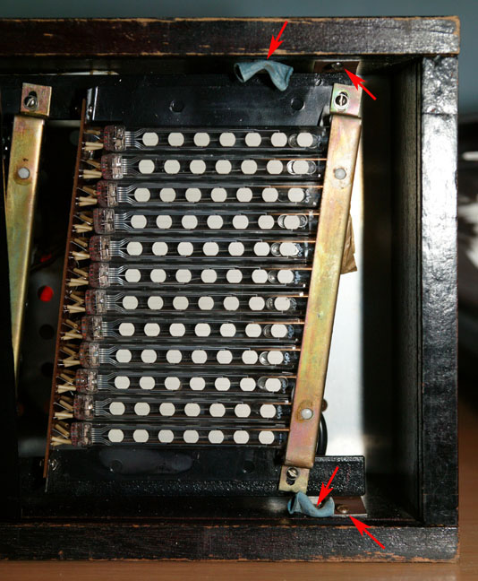
After removing the glass and setting it aside in a safe location, I carefully worked the control panel through the gap on the loose side piece and set that piece of wood aside. With the glass removed, I saw 6 pieces of blue plastic tubing screwed to the inside of the case, presumably to help prevent shocks from cracking the glass. When I removed the 6 screws holding those in, only 4 screws remained, one near each corner of the frame.
Those 4 screws held the frame to the case via flexible metal tabs. After removing them, I was able to carefully pull the frame a few inches out of the case. There were still 2 wires attaching it to the battery compartment, which I disconnected at the battery terminals. Lastly, I had to work the control panel through the gap on the side of the case. Finally, the frame was free of the case and I could get to work studying it.
The first thing I noticed was that the IV-26 tubes each had 9 wire leads, as if they were Type 1 tubes. All 9 leads on each tube were soldered to the display boards, which is a total of 432 connections! I had expected the tubes to be Type 2, which only have 5 leads and would have reduced the number of connections to 240. Examining a tube more closely, it was obvious that the construction was type 2, as there were internal connections between dots 1-2, 3-4-5, and 6-7. It is a mystery why the tubes were built with additional, non-functional pins. Later, while I was replacing the tubes with new ones, I discovered that the tubes were labeled ИВ-26, with no type designation. The date code was IV-84, the format used on earlier tubes where the month was written with Roman numerals. Like the 7-06M in the previous article, the tubes carried the Orzep manufacturer logo. The newer 11-tube version uses Type 2 tubes with only 5 pins, and its display boards only have holes for the 5-pin tubes.
Operation
The clock’s operation is almost identical to the smaller clock, with hours, minutes, and run/stop switches. Unlike the smaller clock, the hours and minutes buttons are of the latching type rather than momentary switches. The bright / dim switch found on the smaller version is not present on this clock, which always operates at full brightness. There is a 5-pin DIN connector which provides 9V, ground, a 1 PPS output and a radio data input. The 11-tube Elektronika in my collection has a similar control panel, but of a newer style, similar to the small 7-06M, with rectangular white buttons in a black plastic frame. The 11-tube clock’s buttons are all momentary, even the run/stop buttom. Apparently these clocks were built with whatever switches were on hand at the time of manufacture.
You can download a copy of the manual here (8MB PDF).
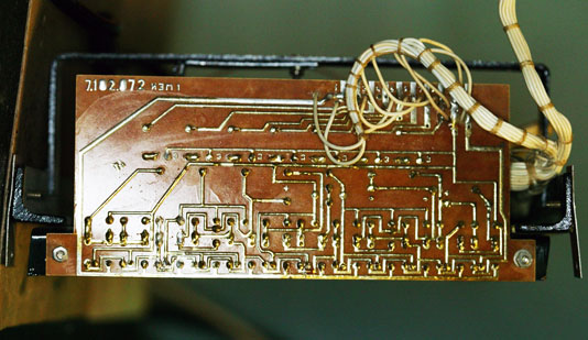
Internal construction
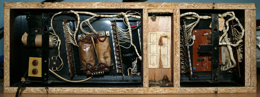
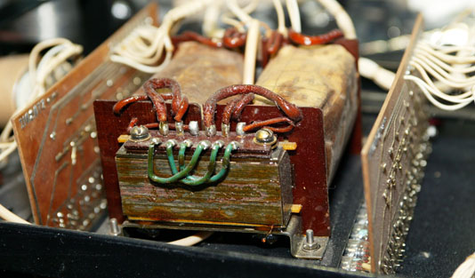
As on the smaller Elektronika 7-06M, all components are mounted to a metal frame which is then attached to the case with 4 screws. As this is a much larger and heavier clock than the 7-06M, the frame has slotted brackets to hang the clock on a wall, whereas the smaller clock just uses slots in the back metal cover, not connected to the frame. To make it easier to identify the internal components, I’ve split the photo into left and right sides to accomodate the column width of this blog.
Clockwise from the left side, the components are:
Two input fuses, one for each leg of the power cord
Filter capacitor
Power supply diode
1’s of minutes decode / display circuit board
Input power transformer
10’s of minutes board
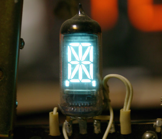
IV-17 colon display tube
Power supply bridge rectifier
1’s of hours board
10’s of hours board
Control panel
Main logic board
The 2 dangling wires in the above photographs connect the clock’s circuitry to the battery compartment. I slipped some heat-shrink tubing over the wires to indicate which wire went to the positive battery terminal and which one went to the negative. As mentioned earlier, the battery compartment is part of the wood case.
The blue and white connectors on the left edge of the main logic board are used for installing the radio synchronization daughterboard, not shown in these pictures. There is a retaining bracket mounted to the frame bracket that runs vertically across the main logic board. This is used to hold the daughterboard in place.
There is an inspection tag (which you can see above the main logic board) but it is nowhere near as complex as the one on the smaller 7-06M clock. This one just has some faded rubber stamps and the date written on it.
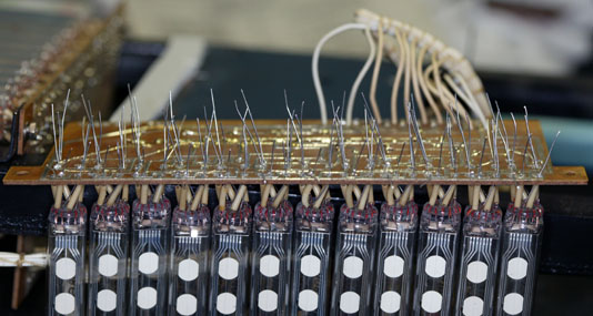
Display
Each digit of the clock has its own circuit board. As with the smaller clock, all circuit boards are single-sided brown phenolic. All 4 of the digit boards are identical – it seems that the economy of mass production outweighed the cost savings that could be realized from using fewer components on the 10’s of hours and 10’s of minutes boards as was done with the smaller clock.
The wiring coming into the display boards provides the filament and anode voltages, along with the signals for the emulated 7-segment display. Diodes are used on the boards to “or” certain display elements together to complete the 7-segment decoding into the 84 individual dots that make up the digit. Of those 84 dots, 18 are never illuminated (the voids in the digit “8”). I have seen pictures of a different version of this clock which show 4 integrated circuits (instead of 7 transistors) on each display board, and using real Type 1 tubes (not Type 2 tubes which have extra, unused pins).
The left sides of the tubes are held rigidly in place by the display circuit board. The right sides of the tubes are held in position by a retaining bracket which is lined with foam, as is the portion of the frame underneath the bracket.
The IV-17 tube used for the colon is just soldered to a 6-pin terminal strip rather than using a circuit board, since all elements are switched on and off together.
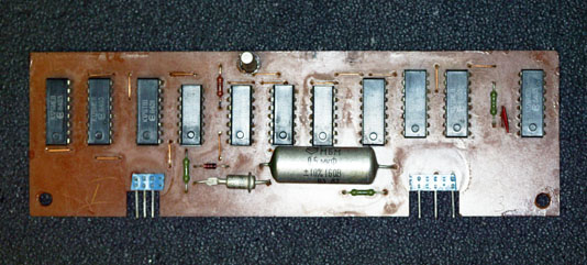
Circuitry
The main logic board on this clock is nearly identical to the one used on the smaller version. Refer to my earlier article for details of the design. The only apparent difference between the two versions is that this clock has a single 2-row connector for the wiring harness, while the smaller clock has a pair of 1-row connectors. The newer 11-tube clock I have in my collection, dated 11-1989, has the pair of 1-row connectors. Thus, this seems to more related to the date of manufacture than the model of clock.
A copy of the schematic is available here (3.5MB PDF).
Radio synchronization
This clock has a DIN connector on the control panel which is used to input a signal to the clock for radio synchronization, which is routed to a plug-in daughterboard. This board is not an actual radio – in fact, it consists solely of digital logic integrated circuits. The connections between the boards provides 9V, ground, 1KHz and 32KHz outputs, as well as the radio signal from the external DIN connector, to the daughterboard and an input from the daughterboard labeled “input correction”. This daughterboard receives audio via the clock’s external DIN connector, and looks for a burst of 6 1KHz tone signals broadcast at the top of each hour. If the logic validates the tones as a proper signal, it will send a “top of hour” correction pulse to the main logic board. The clock will operate on its internal timebase with no external radio signal, and even when the daughterboard is removed.
A newer version of this board with 9 integrated circuits instead of 11 (2 of the decade counter ICs were removed) is used on the 11-tube clock.
The “input correction” signal is very clever, and shows the elegance of the design of the main logic board, which uses only 6 integrated circuits of low complexity. When the “input correction” signal is pulled up to 9V, the minutes (and internal seconds counter, not displayed) are reset to 00. Normally, the hour is unchanged, but if the clock is showing a time between xx:50 and xx:59, the pulse will also increment the hours. This allows the clock to be slow by up to 9 minutes and still be reset to the correct time. Since it is more common that a user would have held the setting button down for too long when setting the time manually, the clock can be up to 49 minutes fast and still correct to the radio time signal at the top of the hour. This worked throughout the Soviet Union as all time zones were in offsets of 1 hour (this was not entirely the case in the rest of the world).
Power
Like the smaller version, this clock is designed to operate on 220V 50Hz. However, the power transformer used in this model can be rewired for 120V operation. One of the 3 green jumpers shown in this picture connects the two primary windings in series for 220V operation.
It is possible to remove the jumper and configure the transformer for 120V. I decided not to do this as I have 220V available and the jumpers were installed by the factory before the transformer was dipped in varnish, so I would have had to cut through the varnish to remove the jumper. I decided to leave the clock as original as possible.
It is interesting to note that this clock has fuses on both sides of the power cord, while the smaller 7-06M only has one fuse on one side of the power cord. I’m not sure why this was done. The newer 11-tube clock in my collection only has a single fuse.
Restoration
Compared to the previous Elektronika, this one shows far more evidence of living a hard life on the wall of some Soviet building. The finish on the case is chipped and the ЭЛЕКТРОНИКА artwork on the glass has some pieces missing as well. A previous owner had added a pair of metal tabs to the back of the case, extending up above the top of the clock, for some reason. It is unclear why this was done, as the spacing between the added tabs is the same as the mounting slots in the back of the case. I set the tabs aside with the other pieces I’d removed / replaced on the clock. I cleaned the case and polished it with furniture polish, but decided to not refinish the wood.
There was evidence that this clock has been in and out of its case multiple times. Quite a few of the screws holding the back plates on were missing and the remaining screws were loose due to being overtightened at some point, stripping out the holes in the wood. While I had the clock out of its case I used toothpicks secured with wood glue to fill all of the holes, then drilled new pilot holes for the screws and installed a full set of replacement screws. Originally, there were 4 plastic spacers that held the back of the clock about 1/2″ away from the wall to prevent the ventilation holes from being obstructed. Two of those had disappeared along the way, so I replaced the two remaining ones and added the missing ones, so now the clock has a full complement of hardware again.
As I mentioned above, the glass slides out of the case once the wood side panel is removed. There were a number of places where the painted black mask had chipped off the inside of the glass. Some of these were around the edges where they wouldn’t be noticed, but there were a number of spots where the missing paint would allow light from the tubes to shine through. After considering a number of possible methods for repairing the paint (including glass paint, black electrical tape, and so forth) I settled on using black UV-cure nail polish. I was concerned about the adhesive in electrical tape reacting with or lifting the original paint, and I was having difficulty locating a glass paint that was guaranteed to stick without invasive surface prep on the glass.
Turning my attention to the display, I replaced all 48 IV-26 tubes. Since the original tubes (and the circuit boards) had 9 pins, I used IV-26 Type 1 (7 individual dots) tubes instead of the 5-pin Type 2 version. This preserved the appearance of the wiring between the tubes and the circuit board. I replaced the tubes in groups of 12 (1 digit) at a time. I inserted the new tubes onto the board, but did not solder them yet as I needed to perform the final alignment with the board back on the frame. As on the Elektronika 7-06M, I reused the original insulating sleeves on the tube leads:
As with the earlier clock, I replaced the degraded orange-brown foam padding with new open-cell foam. With the board back on the frame and the retaining bracket loosely installed, I adjusted the tubes by angling them so they were parallel to the frame of the clock. This is a much easier adjustment than on the smaller Elektronika 7-06M, where there are no real clues as to the needed angle. With the tubes all level, I then adjusted them from left to right so that the columns of dots would show as a straight line. If this isn’t done, the completed display will have a wavy appearance with some dots out of position. Lastly, I made sure that all the tubes were rotated properly so that the dots faced forward. A rotated tube would have dots pointing either slightly upward or downward, which would cause variations in apparent brightness depending on the angle you were looking at the clock from.
Once I had all 3 parameters (tilt angle, extension, and rotation) adjusted on the tubes, I tightened the retaining clamp down to keep the tubes from shifting, and carefully soldered as many tube pins as I could reach – generally the first few rows on each tube – to hopefully lock each tube into position. Next, both the retaining clamp and the circuit board itself were dismounted from the frame so that I could swing the board (with tubes attached) into a position where I could solder the remaining pins on each tube. Remember, there are 108 tube pins on each digit display board. After clipping the excess length of the wire leads and checking to make sure no solder bridges were causing short circuits, I powered up the clock with the display board still dismounted from the frame to check for proper operation. Problems would normally show up as some sections not lighting at all, being permanently stuck on, or by turning on and off when an unrelated section changed. After cleaning up some solder splash left over from desoldering the old tubes with a vacuum pump tool, there were a few whiskers of solder which proved to be troublesome in the tight spaces between the traces on the display board. A quick wash with some board cleaner and a wipe with a bristle brush cleared those problems up, and the digit displays were soon re-attached to the mounting frame and the retaining clamp.
One display board had evidence of a rushed field repair at some point in the past. One of the KT209K transistors that converts the 7-segment drive signals into switching voltage to a group of tube anodes had apparently failed, and a new one was soldered on top of the original leads after the old transistor body was clipped off and discarded. This led to an intermittent problem where different numbers of dots would not display in one of the emulated 7-segment areas of the tubes. There’s a technical reason why the number of missing dots varies – you can post a reply comment if it isn’t obvious from the schematic. I removed the whole replacement transistor and the leads it was soldered to, so that I could install a new KT209K directly through the PC board holes, just like the other 6 on the board. After I’d de-soldered the 3 leads from the display board and gave a gentle tug on the part I was replacing, the transistor and 2 of its extension leads came away cleanly, but one of the extension leads just flopped around the hole in the PC board. Apparently it had never been properly soldered to the transistor when the original repair was done, which is what led to the ongoing problems. Perhaps whoever was trying to repair it decided there was a more complex problem that was not cost- or time-effective to diagnose, and that’s how the clock ended up on eBay. Just a theory, though…
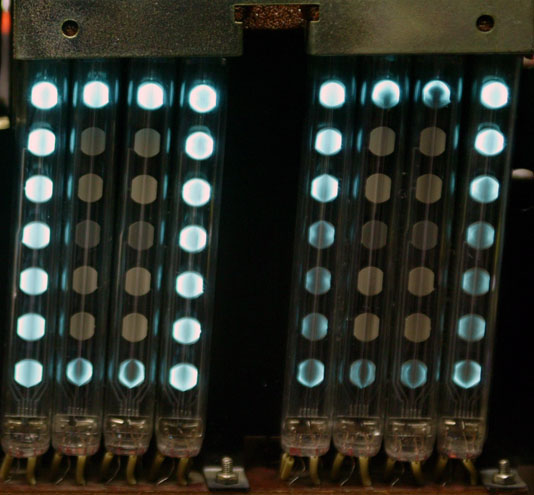
While the existing tubes didn’t seem that dim by themselves, there was a very visible difference in a side-by-side comparison with new tubes:
If you are considering purchasing an Elektronika, you can get a rough idea of the condition of the tubes if you have a photograph of the display. When new, each of the dots will be slightly brighter where the filament crosses the dot. After some hundreds of hours, this will become less apparent, so that the dots are evenly illuminated. As the tubes age, the area under the filament will not illuminate as brightly as the rest of the dot. Eventually this will develop into an obvious dark stripe across the dot. In extreme cases, the dark area will expand to obscure some or nearly all of the dot. This will be accompanied by some darkening of the dot phosphor material when not lit, although there isn’t an exact correlation between this darkening and the brightness level when the dot is lit. Here is a picture (from a different clock) showing a relatively extreme case of tube wear:
It is a simple (but labor-intensive) task to replace the tubes with new ones. The tubes are relatively inexpensive (under $2 each) on eBay at the present time. However, that does mean that re-tubing the big Elektronika will cost over $100 (including the IV-17 tube). When purchasing replacement tubes, make sure you select the appropriate variant (Type 1, 2, or 3) for your clock. Type 2 and 3 are not interchangable. Type 1 will work in all displays, but if the clock was not originally equipped with 9-pin tubes you will need to jumper some tube pins together to form the dot groups. It will be much easier to use the appropriate tube type.
When purchasing replacement tubes, I’d suggest getting a few extra. In the 150 or so tubes I’ve installed so far, I’ve found a few duds. Two of them each had one dot that wouldn’t illuminate. One had an obvious blemish on one of the dots (some sort of contaminant inside the tube) so I didn’t install it. And one other replacement tube didn’t achieve sufficient brightness.
Regarding brightness, there’s a relatively large variation in brightness between different tubes when first used, even from the same manufacturing lot (in addition to the date code stamped on the outside of the tube, there is an additional handwritten code inside the tube itself). This affects all dots within the tube, regardless of how frequently the dots are illuminated. This seems to even out within the first 24 to 72 hours of operation. Even the tubes with the highest initial brightness will become somewhat brighter after a day or so of operation.
As I mentioned in my previous article, use a low wattage soldering iron at the lowest possible temperature as the traces tend to lift off the circuit board when de-soldering. Also, there is no solder mask on these boards – instead, the whole solder side was varnished after soldering. This means that there is varnish covering the solder connections to the tube pins, which will inhibit heat transfer from your soldering iron to the solder joint as well as contaminating the tip of the soldering iron. You’ll need to re-tin the tip before using the iron for other tasks (including soldering the replacement tubes).
Like the earlier clock, this version uses a smaller display tube as a colon between the hours and the minutes. The tube is either an IV-4 or IV-17 sixteen-segment (plus decimal points) display. It was completely unlabeled, with no type or date code markings. Both the 1983 and 1990 versions of the manual state that it is an IV-4. I replaced it with an IV-17, which is identical to the IV-4 except that it is claimed to have a longer life.
You may recall from my previous article on the 7-06M that it arrived with a power cord spliced onto the original short cord, but with bare wire ends instead of a plug. This clock came with a plug, but the wire zipcord it was attached to was very thin – what we’d refer to as “speaker wire”. As with the previous clock, I replaced all of this with a new Europlug cord.
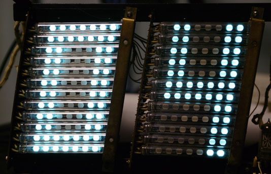
With all 49 tubes replaced, the clock really lights up the room. Unlike the earlier clock, this one does not have a bright / dim switch, so you get full brightness all the time:
The user’s manual for the clock suggests unplugging the clock when there are no people around (for example, at night) and using the batteries for timekeeping while the clock is unplugged. This is because the radio time signal doesn’t tell the clock which hour it is, only that it is the top of the hour. And, of course, if the radio isn’t connected the clock doesn’t even have that information. I’m rather surprised that the clock doesn’t include a display on/off or dimming switch (as was done in the smaller Elektronika 7-06M). Unplugging it seems like a bit of a hack, particularly if it is mounted high up on a wall, adjacent to a dedicated outlet. On the other hand, this probably explains why so many of these clocks have very weak tubes.
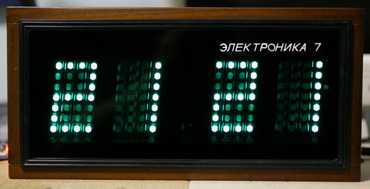
In addition to making Nixie and VFD display tubes, the Reflektor factory in Saratov, Russia built clocks for use in office buildings and other large spaces such as Moscow Metro stations. These were produced under the Elektronika1 7 (Электроника2 7) name. These clocks have a bit of a cult following in the West and were described by Brian Stuckey of TubeClockDB as being “so unique it has its own Wikipedia entry”. While the English Wikipedia article is a rather small orphan article, the Russian Wikipedia has far more information here and here.
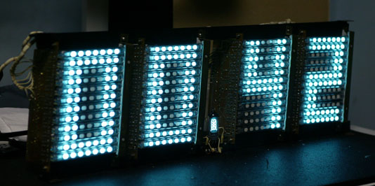
The Elektronika 7 isn’t a single model of clock, but instead is a whole series of clocks of different sizes and functions. The one discussed in this article is the “baby” Elektronika 7-06M. It uses 16 IV-26 Type 3 (ИВ-26 тип 3) VFD tubes, each with 7 dots, arranged as 4 groups of 4 tubes, one for each digit. An IV-6 (ИВ-6) seven segment tube3 serves as the separator between the hours and minutes. The clock is 15″ wide x 7″ high x 2.75″ deep. Each digit is approximately 2″ wide x 3.25″ high.
It is actually quite difficult to get a good picture of an assembled and operating Elektronika 7 due to the highly reflective nature of the glass and the high contrast between the lit dots and the rest of the clock. Digital cameras also have a different color response than the human eye, and the combination of the green-tinged blue of the bare VFDs combined with the green glass makes for a particularly challenging subject. The above picture is a best approximation of the actual appearance and is the result of an actual photograph manipulated in Photoshop. The thin vertical lines adjacent to illuminated dots are caused by the light from the dot reflecting off the glass envelope of the adjacent tube(s).
Here’s a video of the clock during the transition from 23:59 to 00:00. Being a Soviet clock, it only displays in 24 hour mode.
(Click the icon on the top right to go fullscreen.)
Both this video and the photograph above it were shot in “dim” display mode after the tubes had been replaced (see the restoration section later in this article). The still photo has a much more accurate rendition of the display color when viewed through the green front panel glass.
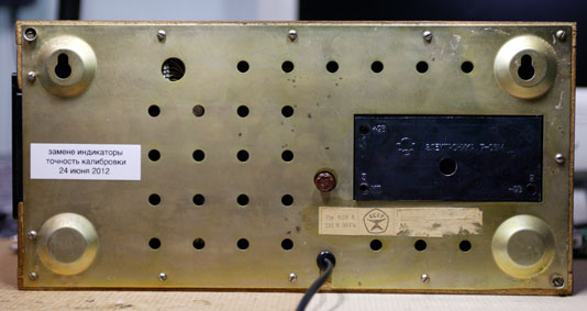
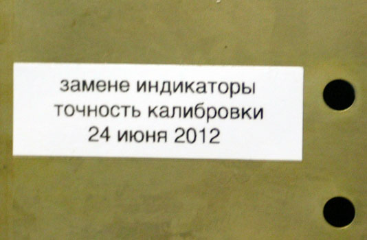
Here’s a view of the back of the clock after I completed my restoration project. The sticker on the right is the original manufacturer / date / serial number sticker, which was defaced at some time in the past (more information later in this article). Above that is the battery compartment door for the backup timekeeping batteries. There are 3 test points on 3 corners of the battery compartment, two for checking the battery voltage and one for (roughly) checking the timekeeping accuracy. Directly above the power cord is a .25A fuse. On the left side I have placed a label indicating that I replaced the tubes and calibrated the clock, along with the date.
In addition to the 7-06M model described in this article, other versions were manufactured with larger displays. I have one with a label reading 7-06 (no suffix) dated 1984 which uses 12 horizontal tubes per digit. I have photographs of one labeled 7-06K dated 1989 which has 11 tubes per digit. This may have been a reduction for cost reasons – more research is needed.
These clocks were manufactured between (at least) 1982 and 1991. The oldest clock I’ve seen has a 1982 date, while the instruction manual (which was supplied with a clock, as it has a serial number written on it) is dated 1991. Production may have started before 1982 or ended after 1991.
The Russian Wikipedia article referenced above states that the clocks were introduced in 1982 and that the K model suffix indicates that the clocks were equipped with a connector for radio synchronization of the time. However, my 7-06 (no K) also has this connector.
Modern versions of the Elektronika clocks are still being manufactured in Russia under the Vesta name. These are available with red or green LEDs or the more traditional VFD (but not with IV-26 tubes, which are no longer manufactured). This is apparently what the soda-can-sized ILC1-1/7 (ИЛЦ1-1/7) 7-segment displays are used for – there is a YouTube video of a 6-digit one in operation here.
Operation
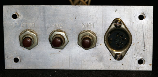
Operation of the clock is quite simple. After plugging it in, the clock will display 00 00 (unless backup batteries were installed, in which case it should retain the correct time) and the colon indicator will be flashing once per second. There is a vertical row of buttons on the right side of the clock case. Refer to the following image for the functions of each button:
МИН – Minutes – Press and hold to increment count 2 times per second, or press once to increment once
ЧАС – Hours – Press and hold to increment count 2 times per second, or press once to increment once
СТОП – Stop – Reset minutes and seconds to 0 and stop counting until released (latching button)
ЯРК – Bright – Dim display while pressed (latching button)
Setting the time involves pressing ЧАС to set the hours, pressing СТОП until your reference time shows 00 seconds and then releasing, and then pressing МИН to set the minutes. Changing the hours or minutes does not affect the (internal) seconds counter.
I obtained an instruction manual from WASP in Kazakhstan. With their permission4, the manual is available for download from my site here (PDF, 16MB).
Internal construction
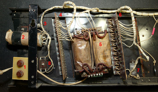
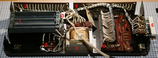
The internal components are all mounted to a metal frame which has 4 metal “ears” which are attached to the cabinet with screws. Refer to this numbered picture to identify each major component:
Clockwise from the left side, the components are:
Compartment for 6 Type 316 (AA equivalent) batteries for timekeeping (but not display) during power outages
Hours decode / display circuit board
1/4A input power fuse
Colon and minutes decode / display circuit board
Buttons for setting time and dimming display
Logic board
Input power transformer (220V input; 23V and 3.2V outputs)
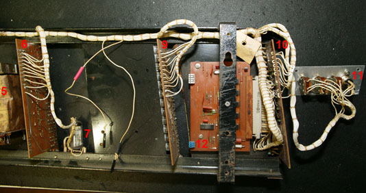
Note the use of connectors on the logic board. I have seen clocks of this model which also use connectors on the two display boards, which was apparently done to make it easier to service the display boards. Strangely, this seems to have been discontinued. My clock has a late 1988 date code, white wires with black lacing cord, and no connectors on the display boards. Another clock of the same model has a mid 1986 date code, green wires with white lacing cord, and connectors on the display boards. The service manual the schematics came from is dated April 1991 and doesn’t show the connectors.
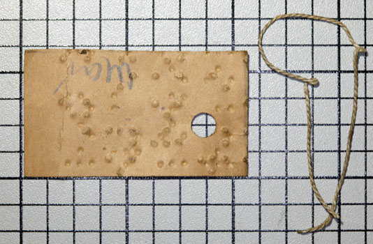
While getting ready to clean the circuit boards, I removed the inspection sticker that was tied to the wiring harness on the minutes board, shown just to the right of the “4” legend in the above picture. It has an odd mixture of dimples (both in and out), rubber stamp, and handwritten markings in both pen and pencil:
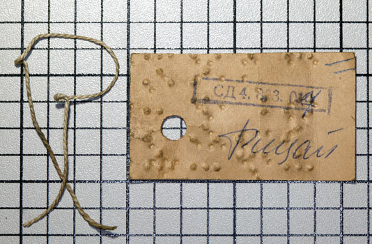
Eremeev Alexey wrote in to say: “I have just little note about “inspection sticker that was tied to the wiring harness…………. It has an odd mixture of dimples” actually its not odd dimples, it iss recycled paper from old books for blind people (Braille writing system). Suspect so it was because many disabled people work (often work in Soviet Union time) on electromechanical plants and they assembled more or less simple devices such wall sockets and switches. Such job may had in nearby worskhop in factory and they may had lots of useless braille paper documents.”
Display
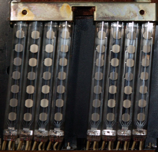
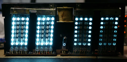
As mentioned above, the clock uses IV-26 tubes for the display:
IV-26 tubes were manufactured in 3 variants. The Type 1 has individually-addressable dots while Type 2 has internal connections between dots 1-2, 3-5, and 6-7. Type 3 has internal connections between dots 2-3 and 5-6. Type 2 was used to create numeric displays from horizontal tubes and Type 3 was used to create numeric displays from vertical tubes. This was presumably done to reduce the amount of assembly labor, as a clock with 16 Type 1 tubes would have 144 soldered connections, while a clock with 16 Type 3 tubes would only need 112 soldered connections. That isn’t a huge savings, but on the 12-tube-per-digit 7-06 version (to be discussed in a later article) the connection count drops from 432 to 240. (The percentage saved varies because a Type 3 tube has 7 pins while a Type 2 tube only has 5 pins.)
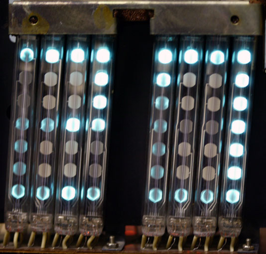
After operating for over 20 years, the various dots within the tubes have faded from use. This varies depending on how often a particular dot is illuminated, and the fading of the dot is accompanied by a darkening of the phosphor material. This does not correspond exactly to the fading of the dot as you can see in the following two pictures of the same tubes when off and lit:
Circuitry
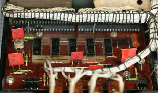
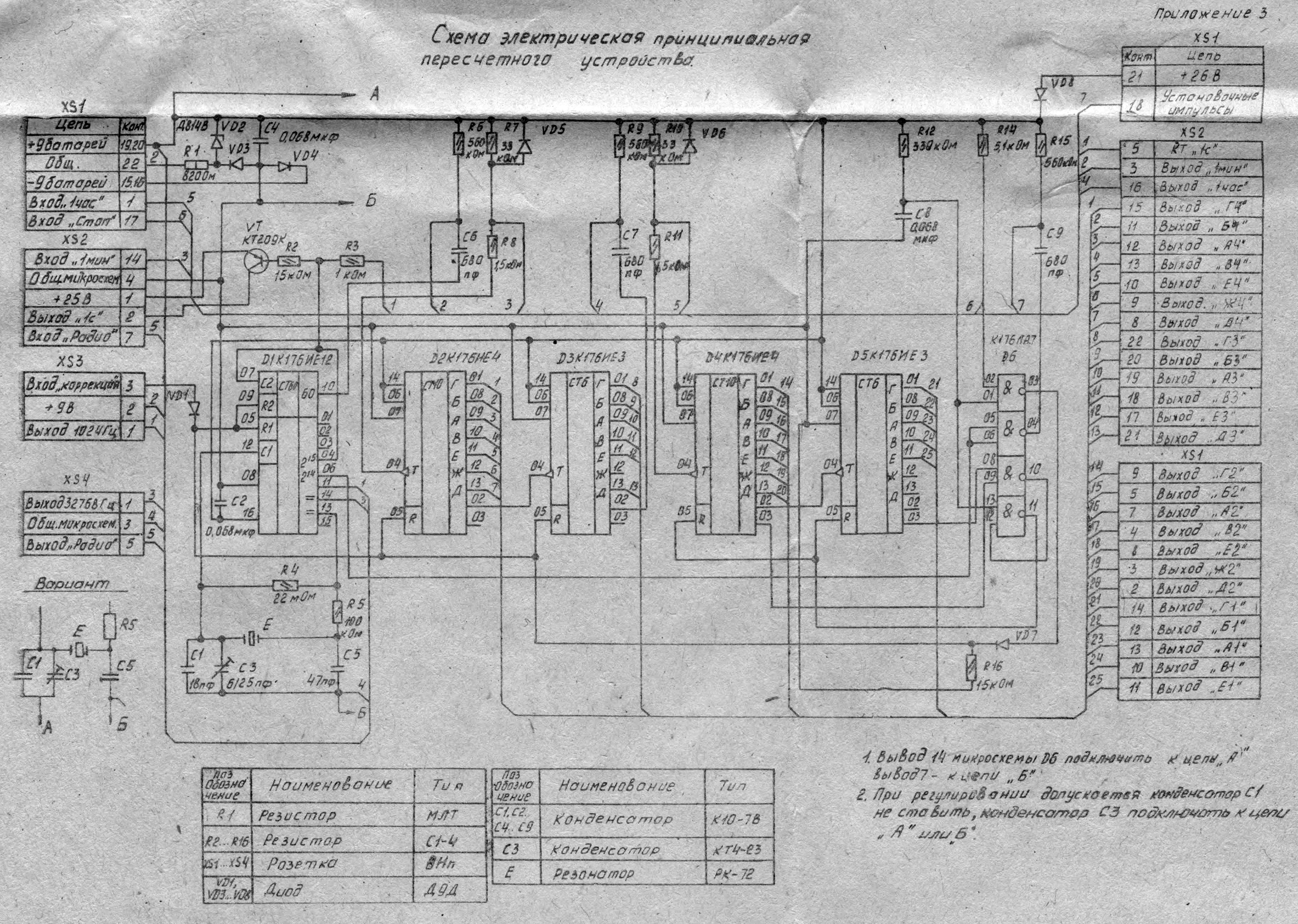
Given the somewhat bizarre use of IV-26 tubes to create a pseudo-seven-segment display, I assumed that the circuitry would be equally Byzantine. It is actually very elegant. The same circuit board is used in multiple clock models, since the timekeeping is separate from the display decoding and drive. It has features not used in the 7-06M – for example, connectors for a daughterboard to process an external radio synchronization signal.
The circuit board contains 6 integrated circuits which operate at 9V (not standard 5V TTL levels). They are:
K176IE12 (К176ИЕ12) – 15-bit frequency divider with 1PPS and 1PPM outputs
K176IE4 (К176ИЕ4) – Modulo 10 counter with 7-segment output (2)
K176IE3 (К176ИЕ3) – Modulo 6 counter with 7-segment output (2)
K176LA7 (К176ЛА7) – Quad 2-input NAND gate
The timebase is generated by a 32KHz RK-72 (РК-72) crystal, known colloquially as a “boat crystal” due to its shape. A trimmer cap provides adjustment of the frequency for accurate timekeeping.
[Click on the schematic for a full-size version.]
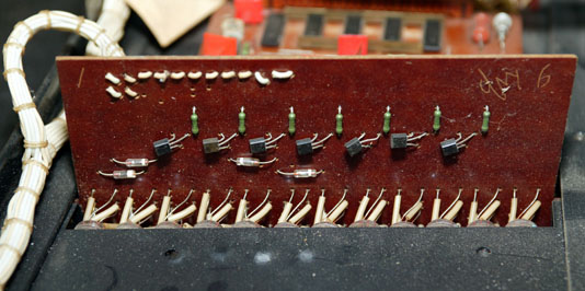
The display boards use a series of KT209 (КТ209) PNP transistors to switch the 25V drive to the tube dots on and off, controlled by the 9V logic levels from the main logic PCB. The 1’s of hours and 1’s of minutes each use 7 transistors, one for each of the emulated 7-segment display elements. The 10’s of hours only uses 5 transistors as this digit only needs to display 0, 1, or 2. The 10’s of minutes uses 6 transistors as the possible digits are 0 through 5. There’s a bit of a clever trick with four diodes on the leftmost tube on the 1’s of hours and both minutes to complete the 7-segment decoding. The 7-segment tube used as the colon display receives its voltage from a KT209 transistor located on the main logic PCB. I’m not sure why this was done – there is certainly enough room on the minutes display board for an additional transistor. Refer to the complete schematic set (PDF, 13MB) for additional information.
Power
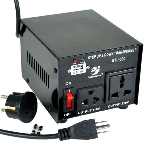
Since this clock comes from Russia, it operates on 220V 50Hz power. Fortunately, it doesn’t rely on the AC line frequency for timekeeping so the 60Hz power in the US is not a problem. However, it does require 220V and won’t work on regular wall power here. For testing, I have a Goldsource STU-300 (Amazon link) power converter. This is a true transformer-based voltage converter and not a simple adapter plug (which wouldn’t work). 300 Watts is massive overkill for this clock (the manual says it consumes 20W). However, this is a nice adapter to have around as it has a regular US 5-15P plug on it and has universal receptacles on the front.
[Stock photo from amazon.com]
After I finished restoring the clock, I plugged it into a large Symmetra UPS I have in my server room. That UPS has 220V outputs as well as the normal 120V ones.
Restoration
As I mentioned above, the tubes had become dim with age and for the best appearance I decided to replace them with NOS (new old stock) tubes. I used the same Type 3 tubes that were used originally in order to keep the wiring identical, and I also re-used the original insulating sleeves. There were strips of orange-brown open cell foam which were used along the tops of the IV-26 tubes to prevent damage during shipment. Like most foam from that era, it had denegerated into a sticky goo that would not spring back once pressed. The same foam was used on the inside of the battery compartment cover. I replaced all of this with a modern grey open cell foam trimmed to the same dimensions, after cleaning off the residual goop from the frame. Since I was replacing all 16 IV-26 tubes, I decided to replace the IV-6 colon tube for completeness. I was concerned that while it originally looked fine, it would appear dim when contrasted with the new IV-26 tubes. While the tubes were removed, I carefully cleaned the black metal plate behind them.
I decided to replace the tubes 8 at a time (one board’s worth). In addition to giving me a good reference for what the positioning should be, this also allowed me to take the following photograph, which shows just how badly the tubes had deteriorated over 20+ years of operation:
I noted with interest that both the original IV-26 tubes and the replacements I installed were manufactured by Orzep, not Reflektor, despite the two companies being competitors (or at least as much as there was competition in the Soviet system). Both the original IV-6 colon tube and its replacement were manufactured by Reflektor. A search on eBay (which certainly isn’t definitive) doesn’t show any IV-26 tubes made by Reflektor. In all cases where a logo is visible, it is the Orzep logo. Perhaps Reflektor never manufactured the IV-26 tube type.
If you decide to replace the tubes on your own Elektronika, be very careful as the circuit traces can de-laminate from the PCB. Use the lowest wattage soldering iron and the minimum temperature that will do the job. When inserting the tube pins, watch out for the pins getting stuck on the circuit pads and trying to lift them off the board.
I also blew all of the loose dust out of the internal components. As I worked on each board, I carefully cleaned it with board cleaning fluid and an assortment of hog bristle brushes to dislodge any debris that remained on the board after cleaning with the compressed gas duster.
Next, I used contact cleaning spray to clean the switches that protrude through the side of the case. I also wiped down the buttons with an alcohol pad to remove decades of cigarette smoke, grime, and other things I don’t want to think about that were deposited on the buttons over the years.
Having completed the innards, I turned my attention to the case. My first step was to use a spray on wood cleanser / polish to remove the decades of built-up gunk. After several coats and buffing the wood to a nice finish, I moved on to the inside of the case. Again, I used the duster to blow loose material out of the inside. I gave the interior wood a quick wipe to remove some more of the dust, but concentrated most of my efforts on the front glass5. Using a streak-free cleanser I removed an amazing amount of grime from the inside of the glass. If you do this on your own Elektronika, please use caution as the black paint mask on the inside of the glass is relatively fragile. You don’t want to either dissolve or chip it. I then repeated the glass cleaning on the outside. The caution about being gentle applies doubly here – the Электроника 7 lettering on the front is also quite fragile. Once I had a perfect streak-free glass, I cleaned the plastic surround with alcohol wipes and cotton swabs to get into the crevices and seams.
The bezel for the control buttons had been removed as part of the procedure for extracting the internal frame from the case. It received the same alcohol cleaning that had been used on the buttons and the display surround.
The remaining case components were the rear metal panel and the battery box cover. These received a quick wipe-down to remove any surface crud, being careful to not damage the serial number / warning sticker any further (the model and serial information had been defaced at some time in the past, presumably to keep the source of the clock secret if it was found in an unauthorized location).
My last step was to replace the taped-on power extension cord with a 2-wire Europlug cord. As these clocks were designed to hang on walls, the orginal power cords were probably quite short – I’ve never seen one with an original cord longer than a foot or two. Normally the people who salvaged the clocks would attach a power cord to the original cord, using varying levels of skill and safety. When this particular clock was delivered to me, it had an original 1 foot power cord and another 10 feet of power cord attached with electrical tape. There was no plug on the end, though, just some bare wires hanging out. This needed to be cleaned up for both safety and aesthetic reasons.
I wasn’t able to locate a new power cord with an attached plug in the same off-white color that was originally on the clock. However, I did find a nice 6′ 2-wire Europlug cord in black, in the same flat style as the original cord (most power cords these days are round). It is a model 10W1-13306 (Amazon link), intended for use with notebook computers. A quick removal of the receptacle and some soldering gave me a nice new power cord for the clock. While this isn’t the exact same type of plug that was used in the Soviet Union, it still allows the clock to be plugged into a Russian outlet and operate.
After all this, I felt that the clock deserved a label indicating that it had been restored to as-new condition, so I made one up (in Russian, of course) and attached it on the left side of the back panel:
Timekeeping accuracy
As received, the clock gained about 2 seconds per day. I mentioned earlier that the timing source is a 32KHz crystal and adjustable capacitor. These were never terribly accurate, and this clock is well over 20 years old and has probably never been adjusted since it left the factory.
I used a frequency counter to adjust the timing with the capacitor. I had some concern that the capacitor would fail during the adjustment due to dust or other stuff getting between its plates. I’ll monitor its accuracy over the next month or so, and if it still gains or loses time (particularly with changes in temperature), I’ll probably design a board to plug into the clock’s unused external timing input. A DS32KHZ temperature compensated timing IC will provide a clock with an accuracy of 1 minute per year (better than .16 seconds / day).
Teaser
Look for an upcoming article on this clock’s big brother, the 48-tube Elektronika 7-06:
Footnotes
[1] Pronounced ee-lec-TRON-ee-kuh. Not uh-lec-… or eh-lec…
[2] Each time I first reference a Russian part number, I enclose the Cyrillic spelling in parenthesis. This is mainly to help search engines locate this page.
[3] The colon tube is actually an IV-6, not an IV-8. This has been confirmed on both my clock and the schematics – the Russian Wikipedia article is wrong.
[4] The WASP site states “I don’t mind when my articles are used on other web resources [in] the Internet community, certainly an indication of the author and links to my site are very welcome. The use of my material in the paper press or advertising material is different and requires permission from the author – write [to me], [as I] reply to all [inquiries].”
[5] An original Elektronika 7-06M will have a sheet of green glass (not plastic) with black paint on the inside to mask out everything but the tubes. If you see an Elektronika 7-06M with plastic or clear glass, it has been modified at some point in the past. The same is true of most other Elektronika 7 models, though some were built with MTH90 (МТХ90) thyratron displays which would need an orange filter.
My goal is for this blog to be the most complete source of information about the Elektronika 7 in any language. I welcome comments / suggestions on how to improve this article.