The Big Elektronika
In a previous post, I covered the small (relatively speaking) Elektronika 7-06M clock. At the other end of the scale is today’s topic, the Elektronika 7-06 and 7-06K. For background info, consult my prior article as I won’t be repeating duplicate info here.
The operation manual says that the 7-06K version includes a radio correction board not included on the 7-06, and that this is the only difference between the 2 versions. All of the big Elektronika clocks I have in my collection include the radio correction board, regardless of whether the label on the back of the clock shows the model as 7-06 or 7-06K. For convenience, I’ll refer to both of these models as “7-06″ here, except when I need to distinguish between them.
The 7-06 is nearly twice as large as the 7-06M. It is 27″ wide x 9.5″ high x 3.75″ deep. The individual digits are 3″ wide x 6” high. It completely dominates any room it is in, both by its size and by the brightness of the display. Even clock collectors who feel that “bigger is always better” might be intimidated by this clock’s imposing presence. The Elektronika 7-06 digits are both taller and wider than the largest CD-47 Nixie tube.
To give you an idea just how large the display is, the clock’s operation manual says that the time is legible from a distance of 75 meters (about 250 feet). That’s before any fading of the display (and may be somewhat optimistic) but I would have no difficulty believing this clock could be read from 100 feet away.
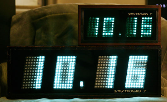
Here is the smaller Elektronika 7-06M sitting on top of the 7-06. Both have new tubes and are running at high brightness (dim mode turned off on the 7-06M, not adjustable on the 7-06). The difference in brightness and dot color is due to the green glass on the 7-06M vs. the clear glass on the 7-06.
Here’s a video of the clock during the transition from 23:59 to 00:00. Being a Soviet clock, it only displays in 24 hour mode.
(Click the ![]() icon on the top right to go fullscreen.)
icon on the top right to go fullscreen.)
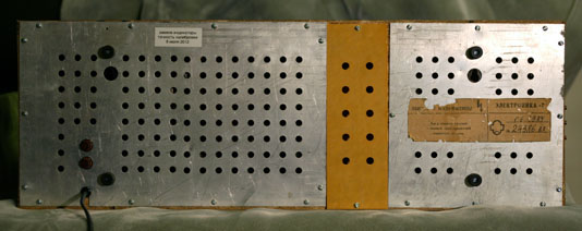
This particular clock bears a label showing the model as “ЭЛЕКТРОНИКА-7” with a date code of “06.1984”. The 06 definitely indicates June, as another clock in my collection has the same abbreviated model number and a date code of “01.1984”. The following picture was taken after I completed my restoration of the clock, replacing the power cord and hardware (screws, bumpers).
There is also a variant of this clock which uses 11 tubes per digit instead of the 12 tubes used in this clock. This introduces an asymmetry in the displayed digits, as there are 2 dark rows of dots on the upper part of the “8”, but 3 dark rows on the bottom part. This seems to have been done on newer production – I have two 12-tube clocks from 1983 and 1984 and an 11-tube one from 1989. The 1983 manual (available below) only describes the 12-tube version, while a newer manual from 1990 only shows the 11-tube version. The 11-tube version seems to have other cost-saving measures as well, such as a lighter internal frame. The case dimensions are exactly the same as the 12-tube version. The paint mask on the inside of the glass is slightly different, as it only exposes the area used by the 11 tubes.
The battery compartment holds 6 Type 373 (D equivalent) batteries for timekeeping during power outages. While the clock will keep time without external power, the display will not illuminate.
The mounting of the electronics / display frame in the case is done in an unusual manner. Unlike the smaller 7-06M where the frame simply comes out the back of the case after removing 4 screws, the 7-06 was initially quite puzzling. After removing the screws that attached the 2 metal back plates and the phenolic battery compartment cover to the case, I could see the circuitry of the clock on the back of the frame, but it wasn’t obvious how to get the frame out of the case. The battery compartment is made of wood and is part of the clock case, so it was obvious the frame couldn’t come out through the back.
However, the front glass was fitted into a recessed groove that ran completely around the case, so there was no apparent method to remove the glass. Operating on the “when in doubt, remove more screws” theory, I unscrewed the 4 screws that held the control panel onto the the left side of the case. These screws were much longer than expected, and when they had all been removed, the control panel could be pulled away from the case. The side panel of the case came along with it, revealing another side panel beneath it. This second panel was fully slotted, so the glass could then be removed by sliding it out to the left.
Unlike the smaller 7-06M clock, the glass on this clock is clear. The black lacquer mask around the display areas has the same construction as the smaller clock, and the ЭЛЕКТРОНИКА lettering on the front is applied in the same manner, though enlarged from the size used on the 7-06M. The clear glass provides a much brighter display than the green glass of the 7-06M, although it does make it easier to see the un-lit dots of the tubes. This was probably done to make the display readable from longer distances. A newer 11-tube 7-06K in my collection has green glass, while both 12-tube clocks have clear glass.
After removing the glass and setting it aside in a safe location, I carefully worked the control panel through the gap on the loose side piece and set that piece of wood aside. With the glass removed, I saw 6 pieces of blue plastic tubing screwed to the inside of the case, presumably to help prevent shocks from cracking the glass. When I removed the 6 screws holding those in, only 4 screws remained, one near each corner of the frame.
Those 4 screws held the frame to the case via flexible metal tabs. After removing them, I was able to carefully pull the frame a few inches out of the case. There were still 2 wires attaching it to the battery compartment, which I disconnected at the battery terminals. Lastly, I had to work the control panel through the gap on the side of the case. Finally, the frame was free of the case and I could get to work studying it.
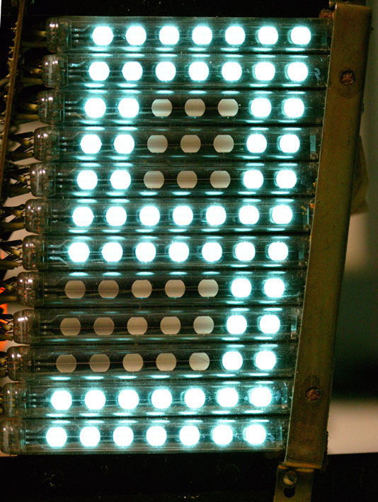
The first thing I noticed was that the IV-26 tubes each had 9 wire leads, as if they were Type 1 tubes. All 9 leads on each tube were soldered to the display boards, which is a total of 432 connections! I had expected the tubes to be Type 2, which only have 5 leads and would have reduced the number of connections to 240. Examining a tube more closely, it was obvious that the construction was type 2, as there were internal connections between dots 1-2, 3-4-5, and 6-7. It is a mystery why the tubes were built with additional, non-functional pins. Later, while I was replacing the tubes with new ones, I discovered that the tubes were labeled ИВ-26, with no type designation. The date code was IV-84, the format used on earlier tubes where the month was written with Roman numerals. Like the 7-06M in the previous article, the tubes carried the Orzep manufacturer logo. The newer 11-tube version uses Type 2 tubes with only 5 pins, and its display boards only have holes for the 5-pin tubes.
Operation
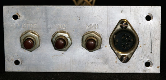
The clock’s operation is almost identical to the smaller clock, with hours, minutes, and run/stop switches. Unlike the smaller clock, the hours and minutes buttons are of the latching type rather than momentary switches. The bright / dim switch found on the smaller version is not present on this clock, which always operates at full brightness. There is a 5-pin DIN connector which provides 9V, ground, a 1 PPS output and a radio data input. The 11-tube Elektronika in my collection has a similar control panel, but of a newer style, similar to the small 7-06M, with rectangular white buttons in a black plastic frame. The 11-tube clock’s buttons are all momentary, even the run/stop buttom. Apparently these clocks were built with whatever switches were on hand at the time of manufacture.
You can download a copy of the manual here (8MB PDF).
Internal construction
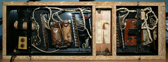
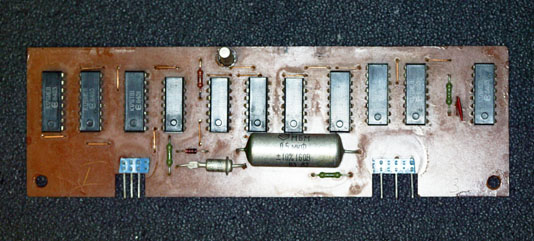
As on the smaller Elektronika 7-06M, all components are mounted to a metal frame which is then attached to the case with 4 screws. As this is a much larger and heavier clock than the 7-06M, the frame has slotted brackets to hang the clock on a wall, whereas the smaller clock just uses slots in the back metal cover, not connected to the frame. To make it easier to identify the internal components, I’ve split the photo into left and right sides to accomodate the column width of this blog.
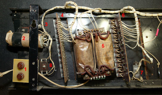
Clockwise from the left side, the components are:
- Two input fuses, one for each leg of the power cord
- Filter capacitor
- Power supply diode
- 1’s of minutes decode / display circuit board
- Input power transformer
- 10’s of minutes board
- IV-17 colon display tube
- Power supply bridge rectifier
- 1’s of hours board
- 10’s of hours board
- Control panel
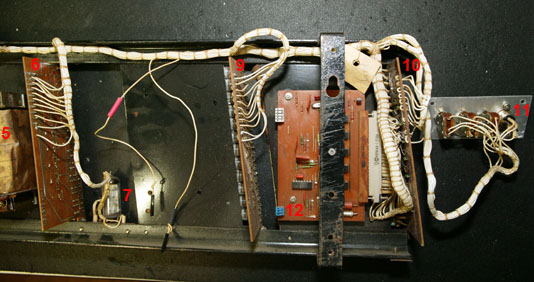
- Main logic board
The 2 dangling wires in the above photographs connect the clock’s circuitry to the battery compartment. I slipped some heat-shrink tubing over the wires to indicate which wire went to the positive battery terminal and which one went to the negative. As mentioned earlier, the battery compartment is part of the wood case.
The blue and white connectors on the left edge of the main logic board are used for installing the radio synchronization daughterboard, not shown in these pictures. There is a retaining bracket mounted to the frame bracket that runs vertically across the main logic board. This is used to hold the daughterboard in place.
There is an inspection tag (which you can see above the main logic board) but it is nowhere near as complex as the one on the smaller 7-06M clock. This one just has some faded rubber stamps and the date written on it.
Display
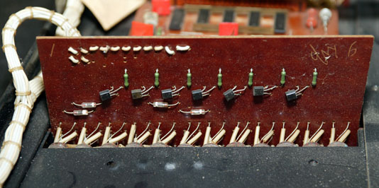
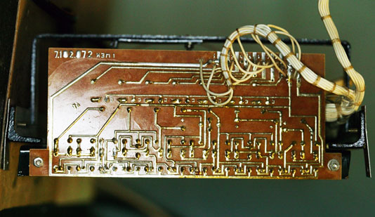
Each digit of the clock has its own circuit board. As with the smaller clock, all circuit boards are single-sided brown phenolic. All 4 of the digit boards are identical – it seems that the economy of mass production outweighed the cost savings that could be realized from using fewer components on the 10’s of hours and 10’s of minutes boards as was done with the smaller clock.
The wiring coming into the display boards provides the filament and anode voltages, along with the signals for the emulated 7-segment display. Diodes are used on the boards to “or” certain display elements together to complete the 7-segment decoding into the 84 individual dots that make up the digit. Of those 84 dots, 18 are never illuminated (the voids in the digit “8”). I have seen pictures of a different version of this clock which show 4 integrated circuits (instead of 7 transistors) on each display board, and using real Type 1 tubes (not Type 2 tubes which have extra, unused pins).
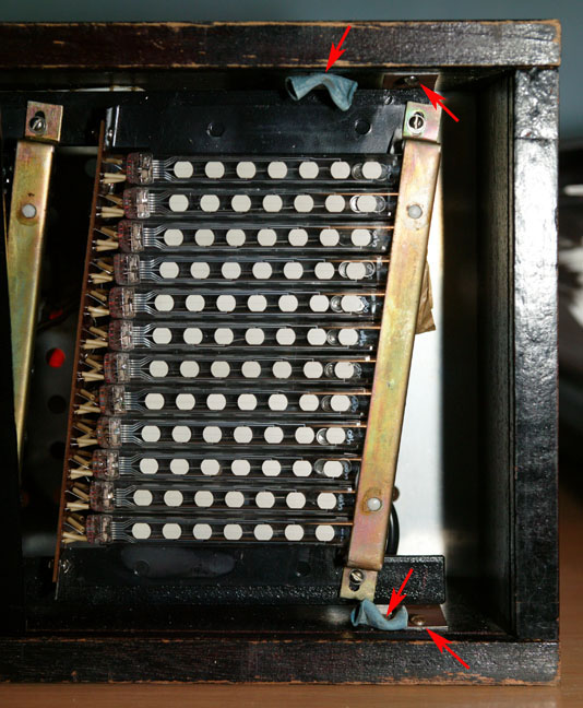
The left sides of the tubes are held rigidly in place by the display circuit board. The right sides of the tubes are held in position by a retaining bracket which is lined with foam, as is the portion of the frame underneath the bracket.
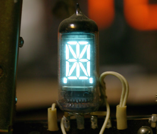
The IV-17 tube used for the colon is just soldered to a 6-pin terminal strip rather than using a circuit board, since all elements are switched on and off together.
Circuitry
The main logic board on this clock is nearly identical to the one used on the smaller version. Refer to my earlier article for details of the design. The only apparent difference between the two versions is that this clock has a single 2-row connector for the wiring harness, while the smaller clock has a pair of 1-row connectors. The newer 11-tube clock I have in my collection, dated 11-1989, has the pair of 1-row connectors. Thus, this seems to more related to the date of manufacture than the model of clock.
A copy of the schematic is available here (3.5MB PDF).
Radio synchronization
This clock has a DIN connector on the control panel which is used to input a signal to the clock for radio synchronization, which is routed to a plug-in daughterboard. This board is not an actual radio – in fact, it consists solely of digital logic integrated circuits. The connections between the boards provides 9V, ground, 1KHz and 32KHz outputs, as well as the radio signal from the external DIN connector, to the daughterboard and an input from the daughterboard labeled “input correction”. This daughterboard receives audio via the clock’s external DIN connector, and looks for a burst of 6 1KHz tone signals broadcast at the top of each hour. If the logic validates the tones as a proper signal, it will send a “top of hour” correction pulse to the main logic board. The clock will operate on its internal timebase with no external radio signal, and even when the daughterboard is removed.
A newer version of this board with 9 integrated circuits instead of 11 (2 of the decade counter ICs were removed) is used on the 11-tube clock.
The “input correction” signal is very clever, and shows the elegance of the design of the main logic board, which uses only 6 integrated circuits of low complexity. When the “input correction” signal is pulled up to 9V, the minutes (and internal seconds counter, not displayed) are reset to 00. Normally, the hour is unchanged, but if the clock is showing a time between xx:50 and xx:59, the pulse will also increment the hours. This allows the clock to be slow by up to 9 minutes and still be reset to the correct time. Since it is more common that a user would have held the setting button down for too long when setting the time manually, the clock can be up to 49 minutes fast and still correct to the radio time signal at the top of the hour. This worked throughout the Soviet Union as all time zones were in offsets of 1 hour (this was not entirely the case in the rest of the world).
Power
Like the smaller version, this clock is designed to operate on 220V 50Hz. However, the power transformer used in this model can be rewired for 120V operation. One of the 3 green jumpers shown in this picture connects the two primary windings in series for 220V operation.
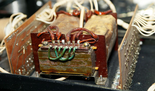
It is possible to remove the jumper and configure the transformer for 120V. I decided not to do this as I have 220V available and the jumpers were installed by the factory before the transformer was dipped in varnish, so I would have had to cut through the varnish to remove the jumper. I decided to leave the clock as original as possible.
It is interesting to note that this clock has fuses on both sides of the power cord, while the smaller 7-06M only has one fuse on one side of the power cord. I’m not sure why this was done. The newer 11-tube clock in my collection only has a single fuse.
Restoration
Compared to the previous Elektronika, this one shows far more evidence of living a hard life on the wall of some Soviet building. The finish on the case is chipped and the ЭЛЕКТРОНИКА artwork on the glass has some pieces missing as well. A previous owner had added a pair of metal tabs to the back of the case, extending up above the top of the clock, for some reason. It is unclear why this was done, as the spacing between the added tabs is the same as the mounting slots in the back of the case. I set the tabs aside with the other pieces I’d removed / replaced on the clock. I cleaned the case and polished it with furniture polish, but decided to not refinish the wood.
There was evidence that this clock has been in and out of its case multiple times. Quite a few of the screws holding the back plates on were missing and the remaining screws were loose due to being overtightened at some point, stripping out the holes in the wood. While I had the clock out of its case I used toothpicks secured with wood glue to fill all of the holes, then drilled new pilot holes for the screws and installed a full set of replacement screws. Originally, there were 4 plastic spacers that held the back of the clock about 1/2″ away from the wall to prevent the ventilation holes from being obstructed. Two of those had disappeared along the way, so I replaced the two remaining ones and added the missing ones, so now the clock has a full complement of hardware again.
As I mentioned above, the glass slides out of the case once the wood side panel is removed. There were a number of places where the painted black mask had chipped off the inside of the glass. Some of these were around the edges where they wouldn’t be noticed, but there were a number of spots where the missing paint would allow light from the tubes to shine through. After considering a number of possible methods for repairing the paint (including glass paint, black electrical tape, and so forth) I settled on using black UV-cure nail polish. I was concerned about the adhesive in electrical tape reacting with or lifting the original paint, and I was having difficulty locating a glass paint that was guaranteed to stick without invasive surface prep on the glass.
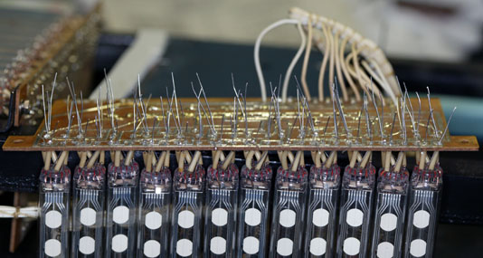
Turning my attention to the display, I replaced all 48 IV-26 tubes. Since the original tubes (and the circuit boards) had 9 pins, I used IV-26 Type 1 (7 individual dots) tubes instead of the 5-pin Type 2 version. This preserved the appearance of the wiring between the tubes and the circuit board. I replaced the tubes in groups of 12 (1 digit) at a time. I inserted the new tubes onto the board, but did not solder them yet as I needed to perform the final alignment with the board back on the frame. As on the Elektronika 7-06M, I reused the original insulating sleeves on the tube leads:
As with the earlier clock, I replaced the degraded orange-brown foam padding with new open-cell foam. With the board back on the frame and the retaining bracket loosely installed, I adjusted the tubes by angling them so they were parallel to the frame of the clock. This is a much easier adjustment than on the smaller Elektronika 7-06M, where there are no real clues as to the needed angle. With the tubes all level, I then adjusted them from left to right so that the columns of dots would show as a straight line. If this isn’t done, the completed display will have a wavy appearance with some dots out of position. Lastly, I made sure that all the tubes were rotated properly so that the dots faced forward. A rotated tube would have dots pointing either slightly upward or downward, which would cause variations in apparent brightness depending on the angle you were looking at the clock from.
Once I had all 3 parameters (tilt angle, extension, and rotation) adjusted on the tubes, I tightened the retaining clamp down to keep the tubes from shifting, and carefully soldered as many tube pins as I could reach – generally the first few rows on each tube – to hopefully lock each tube into position. Next, both the retaining clamp and the circuit board itself were dismounted from the frame so that I could swing the board (with tubes attached) into a position where I could solder the remaining pins on each tube. Remember, there are 108 tube pins on each digit display board. After clipping the excess length of the wire leads and checking to make sure no solder bridges were causing short circuits, I powered up the clock with the display board still dismounted from the frame to check for proper operation. Problems would normally show up as some sections not lighting at all, being permanently stuck on, or by turning on and off when an unrelated section changed. After cleaning up some solder splash left over from desoldering the old tubes with a vacuum pump tool, there were a few whiskers of solder which proved to be troublesome in the tight spaces between the traces on the display board. A quick wash with some board cleaner and a wipe with a bristle brush cleared those problems up, and the digit displays were soon re-attached to the mounting frame and the retaining clamp.
One display board had evidence of a rushed field repair at some point in the past. One of the KT209K transistors that converts the 7-segment drive signals into switching voltage to a group of tube anodes had apparently failed, and a new one was soldered on top of the original leads after the old transistor body was clipped off and discarded. This led to an intermittent problem where different numbers of dots would not display in one of the emulated 7-segment areas of the tubes. There’s a technical reason why the number of missing dots varies – you can post a reply comment if it isn’t obvious from the schematic. I removed the whole replacement transistor and the leads it was soldered to, so that I could install a new KT209K directly through the PC board holes, just like the other 6 on the board. After I’d de-soldered the 3 leads from the display board and gave a gentle tug on the part I was replacing, the transistor and 2 of its extension leads came away cleanly, but one of the extension leads just flopped around the hole in the PC board. Apparently it had never been properly soldered to the transistor when the original repair was done, which is what led to the ongoing problems. Perhaps whoever was trying to repair it decided there was a more complex problem that was not cost- or time-effective to diagnose, and that’s how the clock ended up on eBay. Just a theory, though…
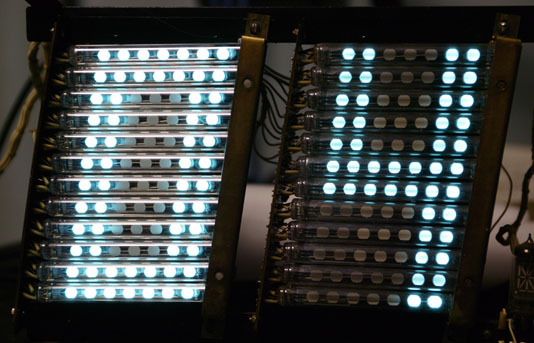
While the existing tubes didn’t seem that dim by themselves, there was a very visible difference in a side-by-side comparison with new tubes:
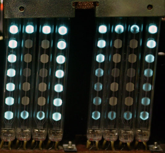
If you are considering purchasing an Elektronika, you can get a rough idea of the condition of the tubes if you have a photograph of the display. When new, each of the dots will be slightly brighter where the filament crosses the dot. After some hundreds of hours, this will become less apparent, so that the dots are evenly illuminated. As the tubes age, the area under the filament will not illuminate as brightly as the rest of the dot. Eventually this will develop into an obvious dark stripe across the dot. In extreme cases, the dark area will expand to obscure some or nearly all of the dot. This will be accompanied by some darkening of the dot phosphor material when not lit, although there isn’t an exact correlation between this darkening and the brightness level when the dot is lit. Here is a picture (from a different clock) showing a relatively extreme case of tube wear:
It is a simple (but labor-intensive) task to replace the tubes with new ones. The tubes are relatively inexpensive (under $2 each) on eBay at the present time. However, that does mean that re-tubing the big Elektronika will cost over $100 (including the IV-17 tube). When purchasing replacement tubes, make sure you select the appropriate variant (Type 1, 2, or 3) for your clock. Type 2 and 3 are not interchangable. Type 1 will work in all displays, but if the clock was not originally equipped with 9-pin tubes you will need to jumper some tube pins together to form the dot groups. It will be much easier to use the appropriate tube type.
When purchasing replacement tubes, I’d suggest getting a few extra. In the 150 or so tubes I’ve installed so far, I’ve found a few duds. Two of them each had one dot that wouldn’t illuminate. One had an obvious blemish on one of the dots (some sort of contaminant inside the tube) so I didn’t install it. And one other replacement tube didn’t achieve sufficient brightness.
Regarding brightness, there’s a relatively large variation in brightness between different tubes when first used, even from the same manufacturing lot (in addition to the date code stamped on the outside of the tube, there is an additional handwritten code inside the tube itself). This affects all dots within the tube, regardless of how frequently the dots are illuminated. This seems to even out within the first 24 to 72 hours of operation. Even the tubes with the highest initial brightness will become somewhat brighter after a day or so of operation.
As I mentioned in my previous article, use a low wattage soldering iron at the lowest possible temperature as the traces tend to lift off the circuit board when de-soldering. Also, there is no solder mask on these boards – instead, the whole solder side was varnished after soldering. This means that there is varnish covering the solder connections to the tube pins, which will inhibit heat transfer from your soldering iron to the solder joint as well as contaminating the tip of the soldering iron. You’ll need to re-tin the tip before using the iron for other tasks (including soldering the replacement tubes).
Like the earlier clock, this version uses a smaller display tube as a colon between the hours and the minutes. The tube is either an IV-4 or IV-17 sixteen-segment (plus decimal points) display. It was completely unlabeled, with no type or date code markings. Both the 1983 and 1990 versions of the manual state that it is an IV-4. I replaced it with an IV-17, which is identical to the IV-4 except that it is claimed to have a longer life.
You may recall from my previous article on the 7-06M that it arrived with a power cord spliced onto the original short cord, but with bare wire ends instead of a plug. This clock came with a plug, but the wire zipcord it was attached to was very thin – what we’d refer to as “speaker wire”. As with the previous clock, I replaced all of this with a new Europlug cord.
With all 49 tubes replaced, the clock really lights up the room. Unlike the earlier clock, this one does not have a bright / dim switch, so you get full brightness all the time:
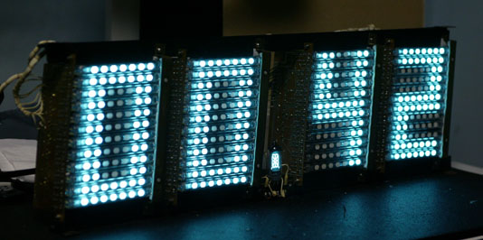
The user’s manual for the clock suggests unplugging the clock when there are no people around (for example, at night) and using the batteries for timekeeping while the clock is unplugged. This is because the radio time signal doesn’t tell the clock which hour it is, only that it is the top of the hour. And, of course, if the radio isn’t connected the clock doesn’t even have that information. I’m rather surprised that the clock doesn’t include a display on/off or dimming switch (as was done in the smaller Elektronika 7-06M). Unplugging it seems like a bit of a hack, particularly if it is mounted high up on a wall, adjacent to a dedicated outlet. On the other hand, this probably explains why so many of these clocks have very weak tubes.
