The haunted IBM 370/138
I’ve written this up several times as a Facebook comment, and each time Facebook has deleted it as “against community guidelines” because I’m quoting someone stuck in
a late 1960s/early 1970s mindset. The two “naughty” words are “God-damn” and “Commie”, so if those offend you, you can stop right here…
SPC had a 370/138 with the IFA (integrated file adapter – DASD controller) and a string of 3340 drives. The operating system (DOS/VS) started throwing “IRREC I/O ERR, UNIT=160, SENSE=********” messages (or something similar, this was 45+ years ago). Since 160 was the system disk, that was a “bit” of a problem as the operating system threw up its hands and quit whenever it happened. The all-asterisk sense data meant that when DOS/VS asked the disk subsystem what was wrong, the subsystem said “Everything is A-OK here!” (the sense only displays bits that were different than expected, with asterisks for status that matched what was expected).
For reference, this is the IBM 370/138 in question. Telephone unintentionally added for scale. And that’s just the CPU, which weighs 2,350 pounds (yes, well over a ton for just the CPU with half a megabyte of memory – we’ve come a long way since then).
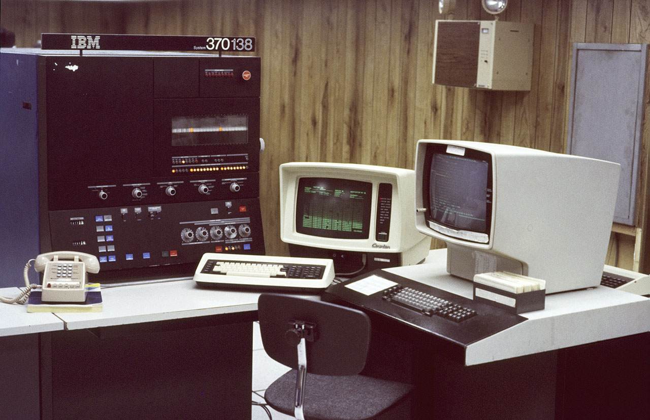
All images are clickable to display a larger version and are by the author unless otherwise credited.
We call our regular CE, Bob. He was an old-timer who bragged that he’d been trained on the IBM 7030 Stretch. He sets up a ‘scope, grabs the appropriate ALD (giant blue book with the schematic, lives in one or more massive rolling carts). He can’t find anything and says he’ll be back the next day.
The next day he and Leon (2nd-level) arrive and have an unproductive day.
On the third day, Bob and Leon arrive with a 3rd guy in a plaid flannel shirt and jeans, and introduce him as Dick. I introduce myself and say “So, they called you in on your day off, huh?” and he replied “No, I’m good enough that I get to dress like this all the time.” No progress is made.
On day four, the three of them are back. As they prepare to leave for lunch, one of them jokingly kicks the CPU cabinet (that’s fine, as I mentioned it weighs over 2000 pounds). Blam! Instant error.
Fortified with lunch, they return and start tapping, but can’t reproduce the problem. They go over to the corner where they think I can’t hear them, and the conversation went like this: “Do you think we should call HIM?” “You know what HE‘s like.” “Yeah, but the customer’s system has been down for a week.” “OK, but YOU call HIM – I’ll go prepare the customer.” One tech walks over to me and says “We’re bringing in somebody tomorrow. Don’t try to talk to him. Better yet, don’t even look at him.”
Day five arrives and the techs arrive, along with a fourth guy. The latest guy is wearing a green herringbone suit worn shiny with age. He looks like they just pulled him out of a tank of formaldehyde – pale blotchy skin. Think of the Borg from Star Trek, but without the cybernetic implants and you’ll get the idea. The three other techs explain the problem, and as they move on to what they tested, he shushes them. He goes over to the console, enters data on the rotary switches, then pushes the “SET ADDR AND DISPLAY” button. Dick pipes up and says “You know, you can do that on the console CRT.” (The 138 was one of very few 370 CPUs with both the traditional lights and switches and a ‘soft console’ CRT). Older designs were lights and switches, newer ones were ‘soft console’ only. “Formaldehyde guy” goes into a rage and yells “I never trusted her – she was a God-damn Commie!” (This is what got Facebook into such a tizzy.)
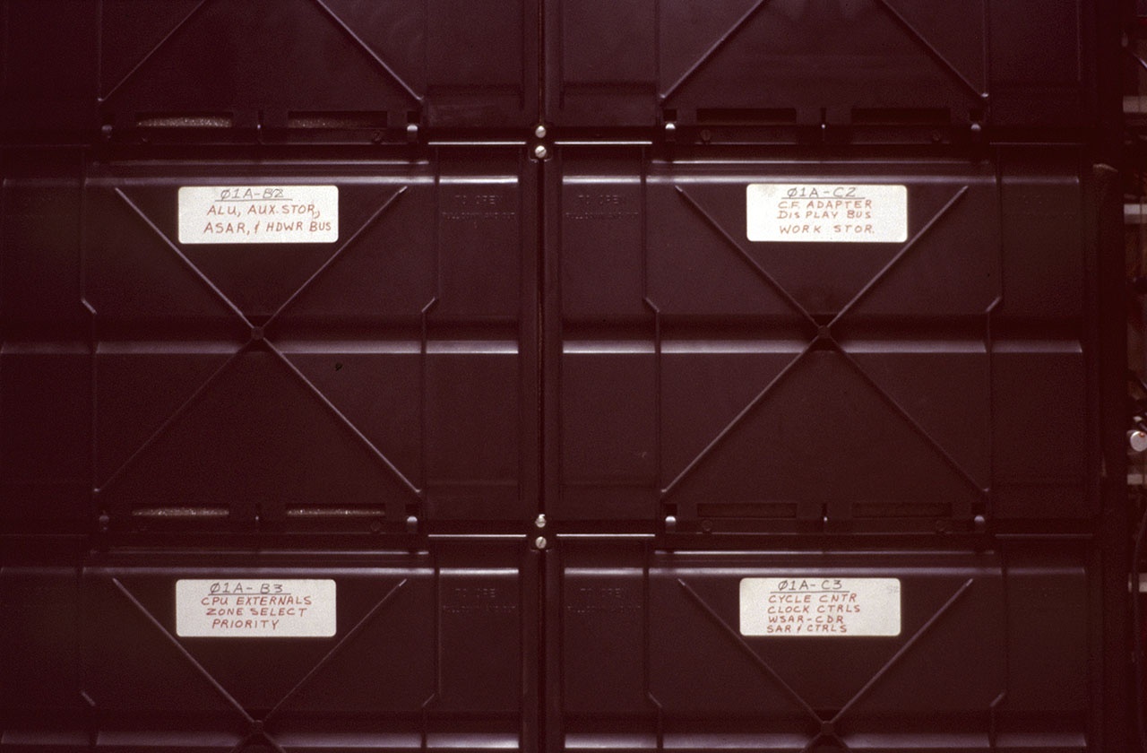
Now, I need to do some explaining with pictures before our story proceeds:
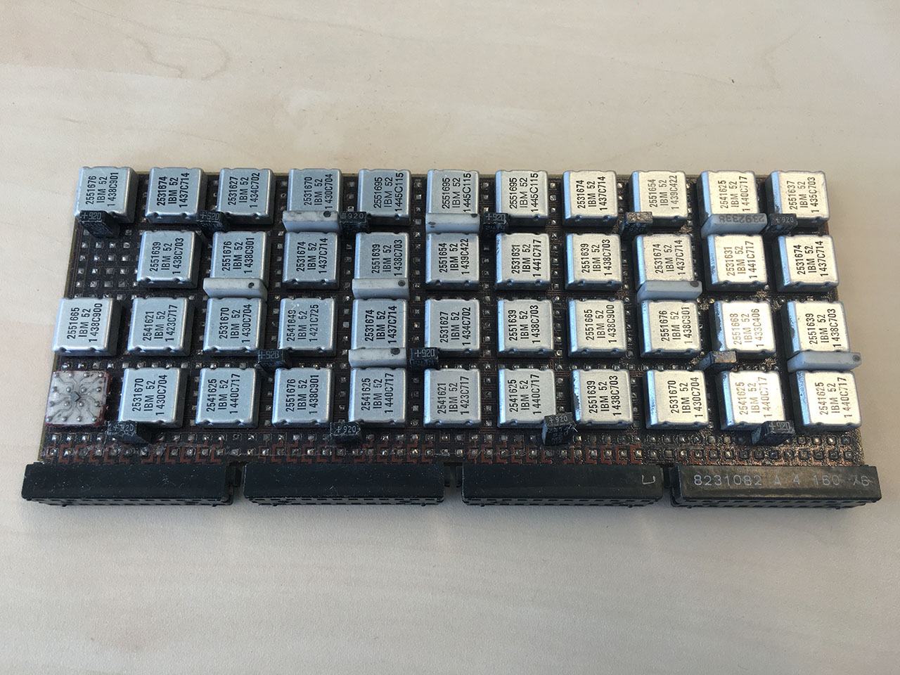
Original image from https://wrabetz.com
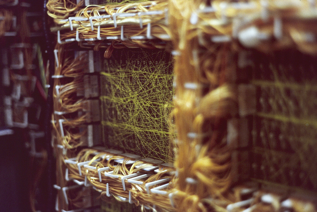
Now that you have an idea of what’s inside the CPU cabinet, the orange-ish wires inside the white plastic fingers around the edges of the card cages are “tri-leads”, IBM’s rather odd idea of how to make a coaxial cable out of ribbon cable.
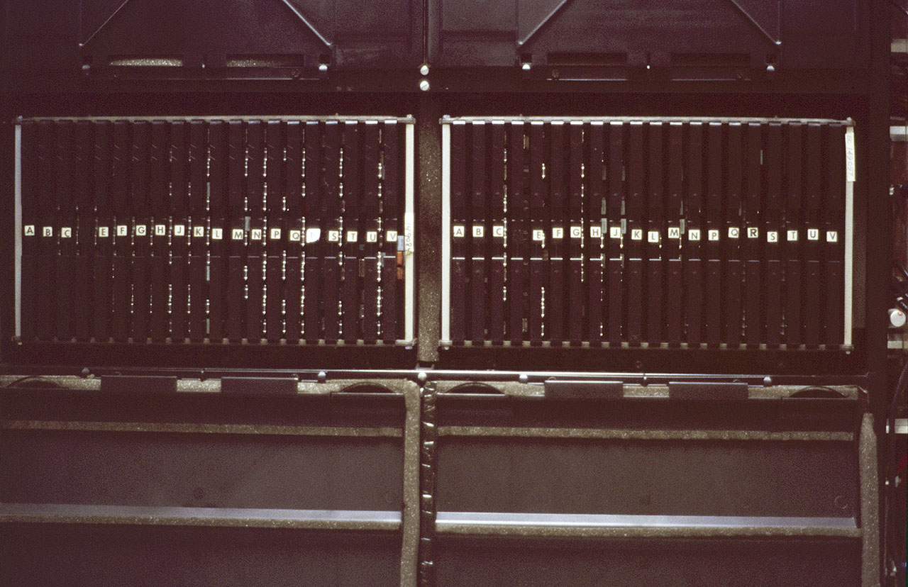
For scale, here is an image of a technician working on a 370 backplane (from a more high-end 370/165 CPU). In the larger version of the image, you can see a hinge in the upper center of the image. The technician and the rolling microfiche cart are actually inside the computer:
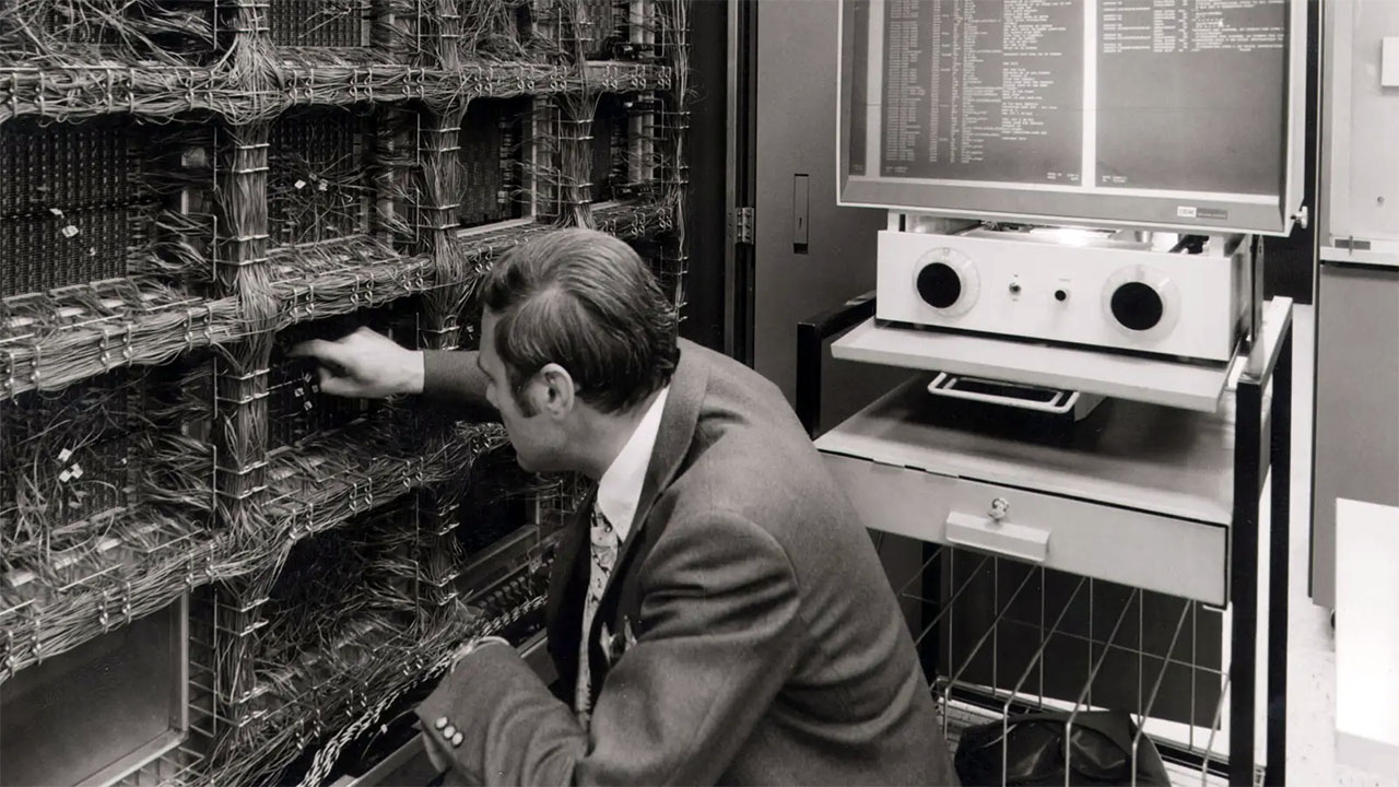
Original image from https://www.bosch.com
After a few more of these set switches / press button / look at lights (during which the other three techs kept completely silent, after unintentionally triggering the previous outburst) he opens the logic gate (the panel with several hundred circuit boards as you can see in the other pictures above), goes around to the wiring side and fishes out a specific tri-lead, yanks it out and says “Change this!”. His next words were “YOU! Drive me to the airport – I have to go to Saudi Arabia!”.
As Leon and “formaldehyde guy” leave, while Bob is replacing the errant tri-lead, I ask Dick “Who the heck was that guy?” Dick replies that he was one of the designers of the IFA in our 370/138. I asked what the shouting was about during the console incident. He sheepishly said “I forgot he didn’t get along with the woman who wrote the console microcode.”
Tri-lead problems were apparently common enough that the IBM Jargon Dictionary has a definition for them:
“Tri-lead trichinosis n. A condition in which the silver signal (centre) conductor of a Tri-lead causes a short-circuit between that conductor and one or both of the adjacent ground conductors due to chemical migration. Nothing to do with the worm infestation resulting from the eating of infected and insufficiently cooked pork, and in no way a religious statement.”
For a somewhat different take on the same type of problem (where kicking the CPU made it work instead of breaking), you can read this article.