Quantum SuperLoader 3 / L700 / PowerVault 124T Power Supply Replacement
The Quantum SuperLoader 3 is a popular tape backup product for small- to medium-size businesses. It combines 16 tape slots, a tape drive (of varying types and capacity) and an operator panel in a compact, 2RU (3.5″ high) format. I often refer to it as “a triumph of engineering over common sense”, as it uses a Rube Goldberg-esque mechanism (including a wheel that rotates as well as moving up and down, along with 2 independent “conveyor belt” mechanisms), but the large number of these units sold over the years proves it was a successful design. It was also re-branded by a number of companies, for example as the Dell PowerVault 124T, Sun StorageTek C2, HP StorageWorks SSL1016, IBM 1×16 Tape Autoloader, and probably by a number of additional companies.
Unfortunately, many of these devices have been installed for quite some time and are now out of warranty. Parts are beginning to fail more frequently than they would when the units were new. One common failure seems to be a completely dead unit – no lights or fan rotation, and no response to the host on either the SCSI or Ethernet port. This is usually due to a failure of the power supply, not anything more serious. Unfortunately, the Quantum Best Practices for Troubleshooting Superloader3 (PDF) says “Is the unit totally dead, no lights, power or sound? If yes – Replace the loader.” That’s a bit expensive if the unit is out of warranty. Even the IBM version doesn’t show the power supply as a field-replaceable unit.
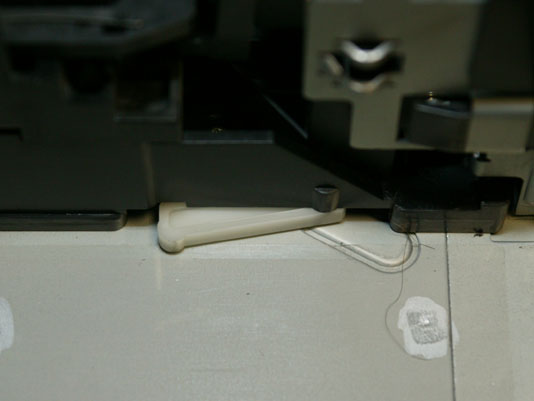
My first step in diagnosing this dead unit was to open it by removing the cover, which involves removing all of the flat-head Torx screws on the left, right, back, and top as well as an additional 4 round-head Torx screws on the top. Next, I manually ejected the left and right tape magazines (since the unit was dead, there was no other way to eject them). The ejection procedure involves sliding a thin piece of plastic (an old credit card will do, but don’t use one you need as you’ll probably damage the magnetic stripe on it while wiggling it around) vertically between the front panel and the magazine. There’s a small white lever on each side which acts as a catch:
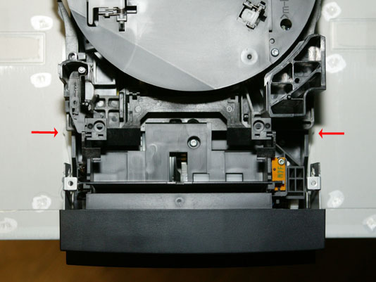
Additional information is available in the Quantum Lodged Tape Removal Instructions (PDF) document. If you cannot eject one of the magazines, it is possible that the magazine drive gear is engaged – refer to the above document for details. In addition to the possibilities listed in that document, it is possible for the loader to have had the power supply fail while in the process of moving a tape from the picker wheel to the magazine – in that case, the magazine can’t be ejected until you remove the loader cover and move the tape fully into the picker (or magazine) by hand.
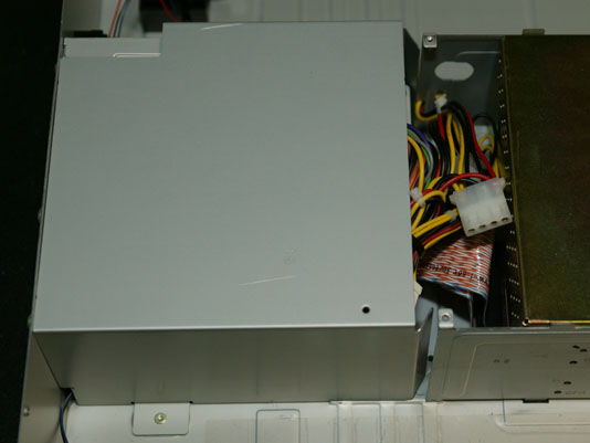
With the magazines removed, there was more room to work inside the unit. Next, I removed the protective cover between the tape drive and the power supply, unplugged the power supply cables to the rear interface board and the tape drive, and lifted the power supply out of the way. This left the power supply connected to the front panel / loader mechanism. There’s a very tight fit between the loader mechanism and the tape drive and one or the other needs to be removed in order to access this cable. I decided to remove the tape drive (the loader mechanism is connected to the rear interface board by a pair of fragile ribbon cables, so removing the tape drive is easier and safer). There are 4 screws holding the tape drive carrier to the chassis, 2 on the back and 2 on the front between the tape drive and the loader mechanism. The front 2 are somewhat difficult to reach. I suggest using an extension and a magnetic Torx bit for this step. Be aware that at this point the tape drive is still connected to the rear interface board via a SCSI cable and the small library interface cable. You can either unplug these and reconnect them later, or just hold the tape drive to the side while dealing with the power cable on the loader mechanism.
Once I was able to disconnect the old power supply from the loader mechanism, I set the old power supply aside and installed a 4-pin Molex power extension cable on the loader mechanism and reinstalled the tape drive, routing the power cable along the same path as the old one:
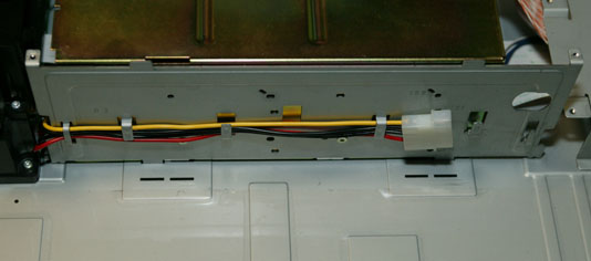
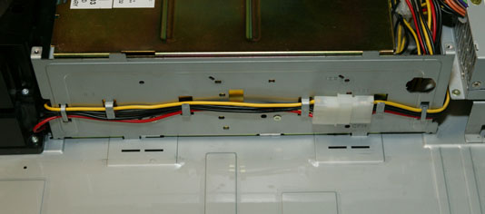
One thing to note in the above picture is the second, unused set of slots in the base pan of the chassis. It appears that some of the possible tape drives that can be fitted are wider than the SDLT600 drive in this unit. If there is no corresponding decrease in the width of the magazine, there may not be enough clearance for the connectors on the type of power extension cable I used. In this case, it would be necessary to use a longer extension cable in order to locate the connectors further toward the back, in the space between the power supply and the tape drive. I used the particular extension cable shown in these photographs because it was the longest one I had on hand, and I didn’t want to make a new, longer one from scratch. Feedback on this issue from users performing the procedure with other drives (particularly LTO models) would be appreciated (use the comment feature).
If you disconnected the SCSI or library interface cables from the tape drive, re-connect them now. Be sure to verify that the cables are located correctly and fully inserted. [I didn’t forget this when working on this loader, but it is a mistake I have made in the past.] If you don’t get both of the cables installed properly, you’ll have to disassemble the whole thing again later to fix it.
Next, I temporarily connected a generic ATX power supply to the rear interface board, tape drive, and the power extension cable for the loader mechanism, in order to confirm that this was a power supply problem:
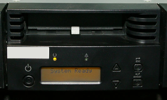
When I connected the AC power cord to the temporary power supply, the loader immediately commenced its power-up sequence to the point where it complained that no magazines were installed. After installing both magazines, the drive completed its power-up inventory and the loader proceeded to the “System Ready” state, as indicated on the front panel. This confirmed that the only issue was the power supply, and the loader simply needed a replacement of the correct type.
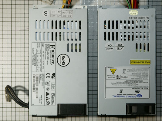
Unfortunately the power supply used in the unit, an Enhance ENP-2316BR, is not available at anything approaching a reasonable price. [As I am writing this, the least expensive one on eBay is $299.95 and the most expensive one there is $795.00. A web search turned up one for $896.00!]
At those prices, it would be less expensive to purchase a whole SuperLoader on eBay (ones with the less-desirable tape formats such as DLT VS160 are currently listed for $299.00 and up) and swap the power supply.
However, I decided to investigate further and discovered that the SuperLoader 3’s power supply is almost a standard FlexATX format unit. The differences are that it has a provision for an external on/off switch and a different quantity and length of power connectors. I initially considered the Enhance ENP-2322B-G as it was made by the same company and shared many characteristics with the original unit. Unfortunately, this series was discontinued by Enhance in June 2011, and any searches for it turn up “replacement” units, not all of which would be physically compatible with the original (mostly relocating the fan and/or changing the location of the mounting screws). I settled on the Sparkle Power FSP200-50PLB (which is not shown on their web site, and the 250 Watt version is labeled “Discontinued soon”), as it had the same fan location, etc. as the original unit. The only issue is that the replacement power supplies do not have cabling for the rear panel on/off switch. However, the loader has an on/off button on the front panel and the rear switch is equivalent to unplugging the power cord. Rather than opening up the replacement power supply, voiding the warranty, and installing switch wires, I decided to leave the rear power switch disconnected and non-functional. This power supply cost $44.99, including shipping – quite a substantial savings from the “best” price of $299.95 for the original supply.
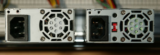
Here are some comparison photos of the old (left or top) and new (right or bottom) power supplies:
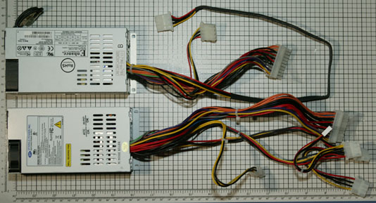
As you can see in the last picture, the new supply has more cables and most are longer (though one is shorter) than on the old supply. That’s why I installed the extension cable on the loader mechanism – I knew the cable on the new power supply wouldn’t reach all the way.
I proceeded to request an eject of the right side magazine via the front panel and then powered down the loader via the front panel pushbutton. The front panel will not respond to any commands other than the power button when either magazine is removed. This makes it impossible to remove the second magazine as the loader insists on having the first magazine re-inserted. After powering down, I performed the manual eject procedure on the left side magazine.
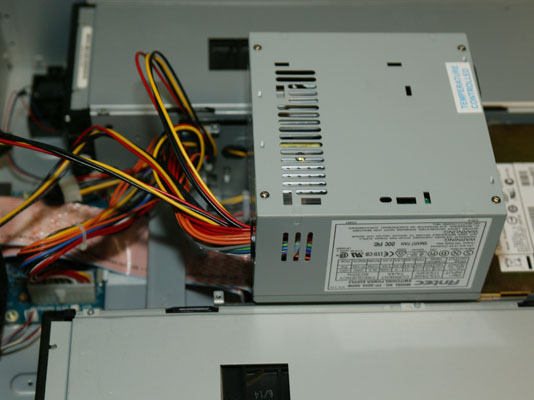
Next, I installed the new power supply, connected all of the cables and neatly tied the excess into a bundle between the power supply and the tape drive. There are several things to note about this step. First is that the bundle of cables should be as low as possible, in order to not obstruct the air vents on the upper rear of the the tape drive. Next is the routing of the power cable to the extension cord installed previously. Use one of the far end connectors from the power supply, not one in the middle of the cable. Ensure that the cable is securely held in the provided tabs – if it comes loose it will interfere with the cycling of tapes in the right-hand magazine. Last is the use of cable ties. Do not use rubber bands or anything besides cable ties. Things are packed quite tightly inside the unit and if a rubber band or similar breaks and starts floating around inside there it could cause serious damage. Once everything was properly placed and tied down, I reinstalled the protective cover / air shroud over the power supply:
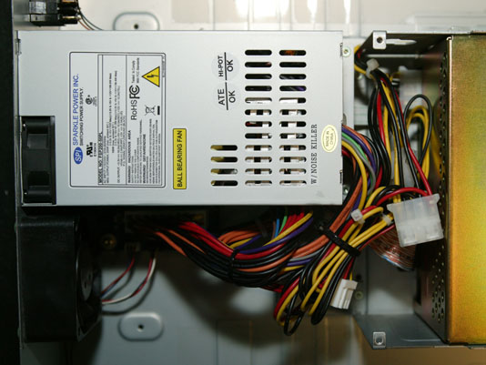
At this point I reinstalled the magazines (checking for clearance where the extension cord connects to the power supply cord) and verified proper clearance of the power supply in the rear panel:
Note that the new power supply has a 115/230 Volt selection switch, while the original did not (it auto-detected the voltage). If the power supply you use has a selection switch, make sure it is set to the proper position for the power you have (in the US, normally the 115V setting, though some datacenters use 230V for efficiency purposes).
Lastly, I powered up the unit and verified that it completed its inventory and proceeded to the “System Ready” state. Once that was completed, I powered the unit down via the front panel and reinstalled the cover. After powering back up, the loader is ready and should hopefully provide many additional years of serivice:
Here are a few additional notes that may be useful if you perform this procedure:
Most FlexATX power supplies of 200 Watts or higher should be electrically compatible with the loader’s requirements. It is important to confirm physical compatibility as well. The main issues will be the location of the power connector and fan opening – some supplies exchange their positions which would lead to a partially-obstructed cooling fan; having a 20-pin ATX connector (some supplies have only the 20-pin, some have a 20-pin and a separate 4-pin, and some have a 24-pin – the first two will work, the last won’t); having a hole for a mounting screw above the power connector location; and having the proper bracket on the cable side of the power supply (if a supply doesn’t have that bracket, you may be able to re-use the one from the original supply, but confirm that there are at least mounting holes for the bracket on the new power supply).
If you get the urge to clean the dust out of the loader while you have it open, be very careful, particularly if you are using a compressed-gas duster. NEVER use compressed gas to spin a fan’s blades – if you must clean a fan, hold the blade so it does not rotate while you use the compressed gas. Also, NEVER used compressed gas on warm electronics. This is particularly important with DLT drives – if you do this on a DLT8000-family drive (for example), you WILL destroy at least one of the tape spool motors from thermal shock. Let the unit cool down, overnight if possible, before dusting.

December 16th, 2011 08:44
[…] Terri’s Random Ramblings » Quantum SuperLoader 3 / L700 …5 days ago … Quantum SuperLoader 3 / L700 / PowerVault 124T Power Supply Replacement. The Quantum SuperLoader 3 is a popular tape backup … […]
June 8th, 2012 00:45
Terri,
This proved invaluable in helping to repair a Dell PowerVault 124T. If anyone else has to go through the same process, you are in the right place. The instructions are spot on. As mentioned, replacement power supplies are ridiculously expensive and it would be cheaper to get a new tape drive. I tested ours with a standard ATX power supply hooked up as well and everything fired right up. At that point I knew the original power supply was bad and the drive was still good.
Here are a couple of thoughts on my experience…
I believe one of the reasons they tell you to “Replace the loader” is because of the excessive number of screws that hold this beast together. It was DEFINITELY NOT meant to be field serviceable. Despite my best effort to pay attention, I ended up with a handful of extra ones when I was done 🙂
Instead of the Sparkle Power FSP200-50PLB, which I believe was no longer available, I ended up with a Sparkle Power FSP200-50PL. It fit like a glove just like the Sparkle Power FSP200-50PLB you had.
I got hung up after reassembling because one of the ribbon cables was not fully connected (which caused the unit not to POST due to mechanical issues). Had I paid more attention to your experiences / advice I would have caught that. But another round of dis-assembly followed by re-assembly did the trick. I paid much closer attention and tested the unit before re-assembling it this time.
Regarding the extension cable: I liked the flatness of the original cable so I kept it. I hacked it off at the power supply end. I hacked off one branch of connectors from the new power supply (mostly to gain a little extra space) and soldered old to new. Seemed a little bit cleaner than having the molex connector next to the magazines. But if you’re not into solder and the connector fits, by all means use it.
Thanks again for the detailed instructions and pictures. This proved VERY handy and economical. Our church thanks you!
Animal
[…] “a triumph of engineering over common sense” […] [HILARIOUS]
June 8th, 2012 14:54
@Animal – I think the reason Quantum says to replace the loader is so they can make money. A while ago they discontinued “free lifetime software updates” on these units and only brought them back recently (and quietly). Perhaps the copy of my order for a $50k LTO library from IBM (NOT based on any Quantum products) changed their minds. I’ve also had problems with Quantum not wanting to honor their lifetime media warranty. The RMA procedure includes listing all of the serial numbers and they will reject any that are “too old” because they would be “worn out”. I had to explain to them that just because a tape is old doesn’t mean it has ever been used, and asked them to look at the load/unload count when they received my RMA. After a good deal of back-and-forth, they agreed to replace the defective tapes “once, as a courtesy”. As you can see, I’m not a Quantum enthusiast any more.
Anyway, the IBM version of the service info (link in my original article) does list part numbers for the various internal components, just not the power supply.
Keeping track of the screws can always be tricky. Taking photographs or having a second unit to refer to always helps. An easy trick is to take an old ice cube tray and number the compartments. Then stick a piece of tape near each screw hole after you remove the screw, and write the same number on it.
Regarding the power extension cable, if I were just doing the repair for myself I would have unsoldered the harness from the old power supply and re-used it on the new supply, as well as re-connecting the rear panel on/off switch to the power supply. However, that’s a bit much to expect of most of the people who read this blog. The idea is to help them do something themself, not scare them away. In some cases where soldering is necessary (like the MegaRAID battery replacement) I do go into the details.
Anyway, I’m glad I was able to save you and your group a lot of money.
Terri
October 3rd, 2012 18:50
I have this same unit with a DLT drive. Now I see some messages in the LCD regarding issues with the FAN.
Backup exec app is now showing temp issues in the log.
Because the unit is out of warranty, Quantum do not want to help me. Do you believe I can replace the fan of this unit? Is this an special fan or regular one like the ones you find in Power supply units?
October 3rd, 2012 19:20
@agarcia2 – These may be real issues or they may be false alarms from the loader firmware. Make sure you’re running the latest firmware for both the loader (V86, as of today) and your drive (varies depending on the model). The download link is currently at:
http://www.quantum.com/ServiceandSupport/SoftwareandDocumentationDownloads/SuperLoader3/Index.aspx
Beware – Quantum tends to redesign their web site and make old links stop working.
The first thing to do would be to see if the fans are actually turning. There’s one inside the power supply and a larger one mounted to the back panel of the loader. If the power supply fan isn’t turning, I’d suggest replacing the whole power supply as things are very tight inside the power supply.
If it is the external fan that’s not turning, you can replace it. Make sure it is plugged into the rear logic board, though – sometimes the cable can become loose. I would suggest looking at the fan to determine the part number and then do a web search for that number. (I no longer have any of these loaders.) When buying a replacement fan, try to use a vendor that is known for selling new products. Depending on the brand of fan, I normally use Digi-Key, Mouser, or Newark Electronics. Random vendors you find via a web search may be selling pulled (“Refurbished”) fans, or may actually be “part miner” sites where you have to sign up to get “bids” (and spam) from many different companies.
November 29th, 2012 10:54
Because this was such a great write-up I decided to try and replace a LTO2 124T power supply but had the mis-fortune to have an LTO4 drive in a 124T chassis fail at about the same time. In order to keep the backups moving I removed the P/S from the LTO2 (SCSI) chassis and replaced it with the one from the LTO4. All works well. Next I find a replacement LTO4 (SAS) drive and buy an Enhance 2232B P/S. I installed the drive and then the P/S in the SAS chassis, power it up….aaaaannnnd…a blank display and an error light. So I test the P/S, swap in a ATX 20 desktop P/S, reset the unit per Dell’s instructions and still nothing but a blank display. Dell indicates a blank display can be caused by re-powering the unit too fast and advises holding the power button down for 15 seconds then unplugging/replugging the unit. Still nothing. I’ve checked all the cables to the board and triple-checked the power unit. All appear normal. I can’t remote to the unit even though it was programmed prior to swapping out the parts. It was unplugged for about 3 weeks while locating the replacement parts. The only difference I noted between the two power supplies(besides the external on/off) was a blue wire that carries -12v according to specs. I disconnected this on the off chance it was causing a problem but still no change. Thought I might pick your brain to see if you had any ideas? Thanks in advance.
December 4th, 2012 19:08
@krispkritter – I don’t have any concrete suggestions for you. Can you test the LTO4 drive in some other system to make sure it isn’t the problem? I no longer have any Superloaders here, so I can’t check to see what sort of behavior you get with a bad drive or no drive – I would expect the display to power up and do something, at least the backlight.