If you buy used Dell servers, you may end up with a system assembled from various parts. One of the more common things is ending up with a server that has no disk trays, or where the drives in the trays don’t match the labels on the trays due to the seller swapping or adding drives.
While the labels on the trays don’t provide enough detail to tell you the exact model of drive in the tray, it at least gives you a clue what you’re looking at, like “SAS 146GB 15k”. I recently assembled a server which came with no drives, by adding 8 Toshiba PX04SMB040 SSDs (Dell part number GM5R3) which came in unlabeled trays.
A number of different solutions have been proposed – everything from writing on the tray with a silver Sharpie pen to web-based label generators. Even if you could generate a perfect printout of tray labels, there is still the issue of finding a printer that can print silver, as well as the issue of either aligning the labels or manually cutting each label to size. Dell prints enough labels (or contracts them out) in large enough quantities that it works for them. I decided I could create a simpler solution at a much lower cost.
Since I already had all of the things needed to create tray labels, I decided to document the procedure here in case anyone else is interested.
First, you will need a Brother P-Touch printer that takes “TZe” type labels and supports printing from a host computer. I have the PT-P710BT “P-Touch CUBE Plus” model.
At the time I started this project, I could not find a Brother part number for a TZe 9mm black print on silver tape. Fortunately there is a huge aftermarket supply of TZe tapes, so this was not a problem. On eBay I found one in sealed packaging for $1.99. While I was writing this article I discovered that Brother does indeed make this size and color of tape – the TZe-M921. But Brother really does go out of their way to make it difficult to find part numbers for their tapes. I think that if they had a simple PDF, updated regularly, with columns showing tape width and rows showing the color, and either a part number or “N/A” at each intersection, they’d sell a lot more tapes.
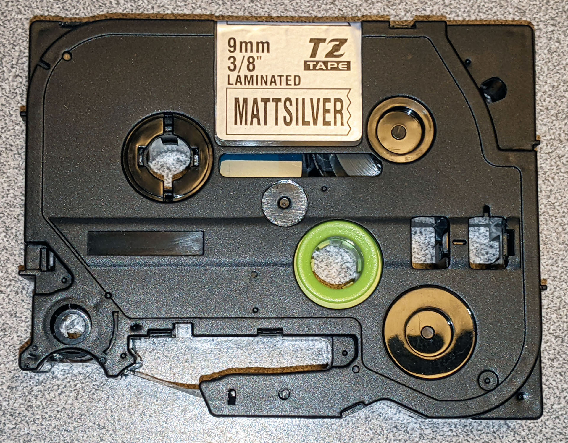
Here is the “MATTSILVER” (sic) tape I purchased on eBay:

All images are clickable to display a larger version.
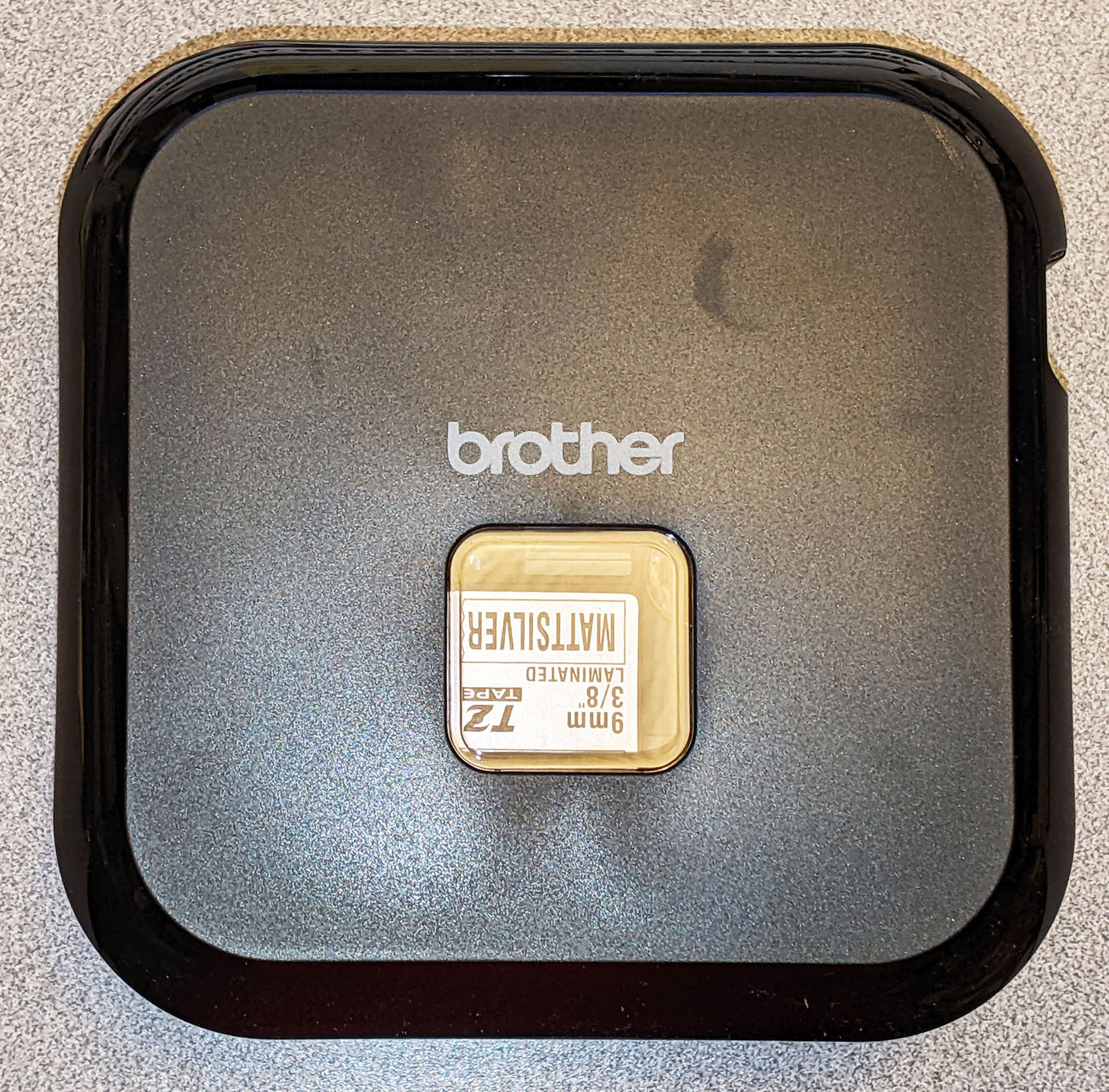
Installed in the P-Touch CUBE Plus:

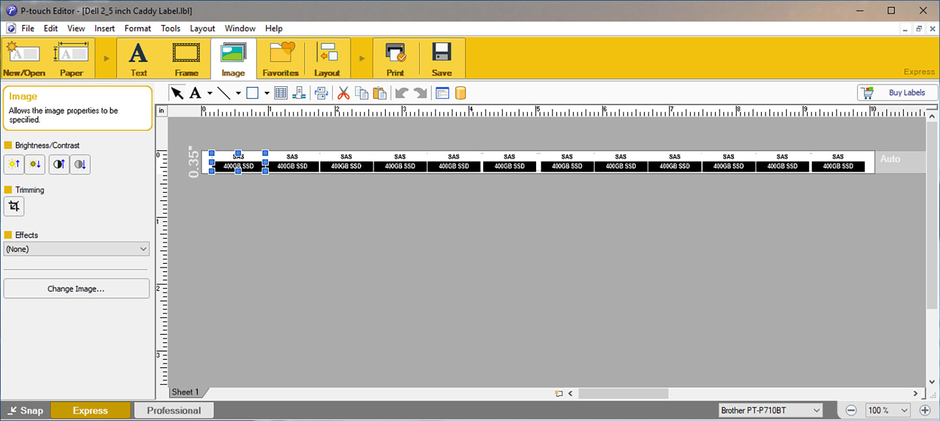
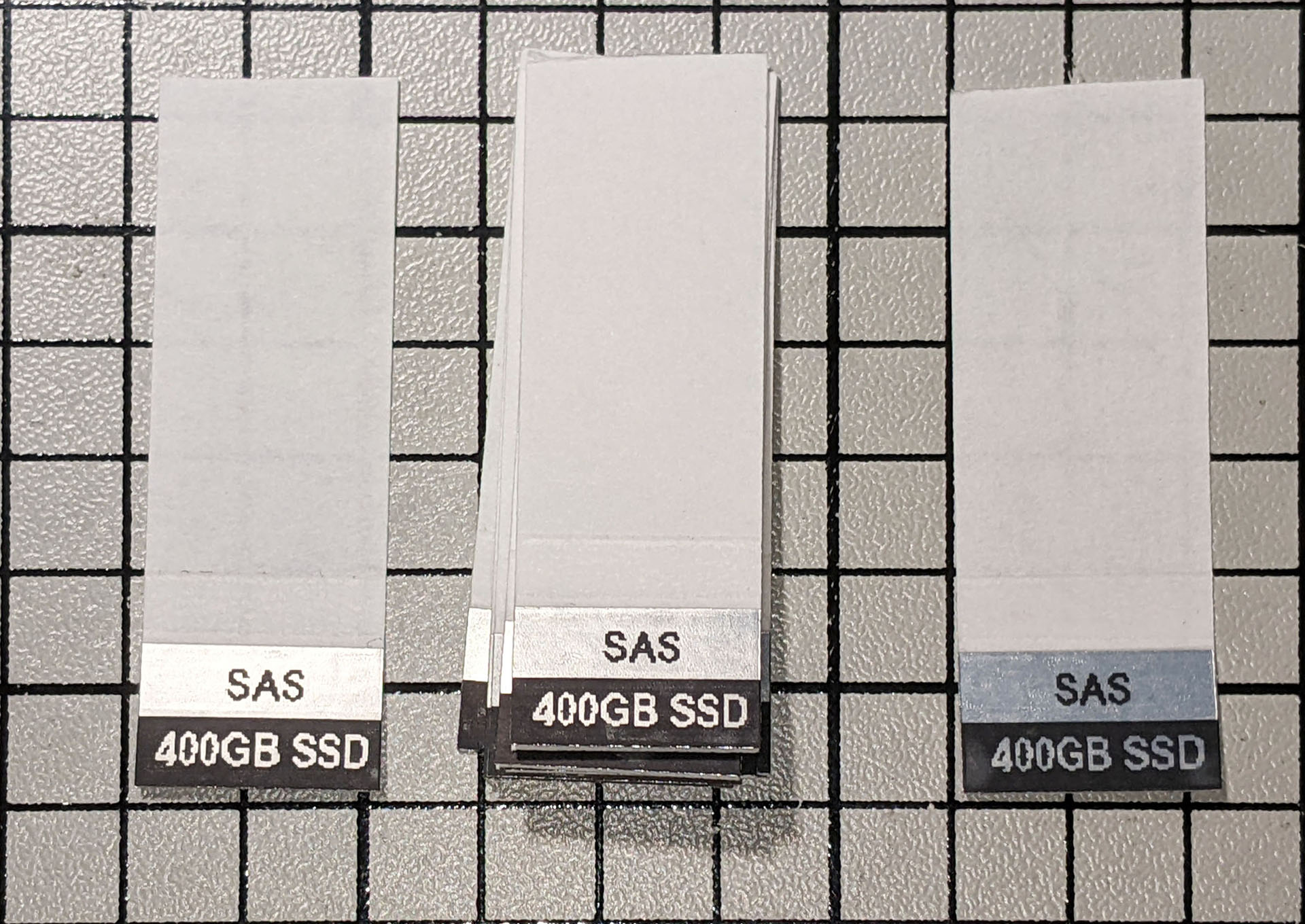
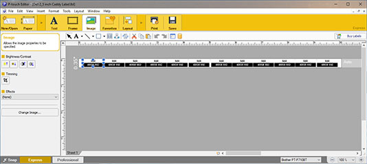
Next, I created an image of the desired label in Adobe Photoshop. You can download the Photoshop file here and modify it to suit your requirements. I then saved the completed image as a .png file and imported it into the P-Touch Editor, duplicating it multiple times to create a strip of identical labels. The P-Touch file for the strip of labels I created is also available here (right-click and “Save Link As…”), although it won’t be very useful unless you also have 400GB SAS SSDs. But you can load it into the P-Touch Editor to see how easy it is to use.
The varying gaps between labels are not important – these will be trimmed away later. What is important is the vertical alignment – the black strips should align across each of the duplicates:
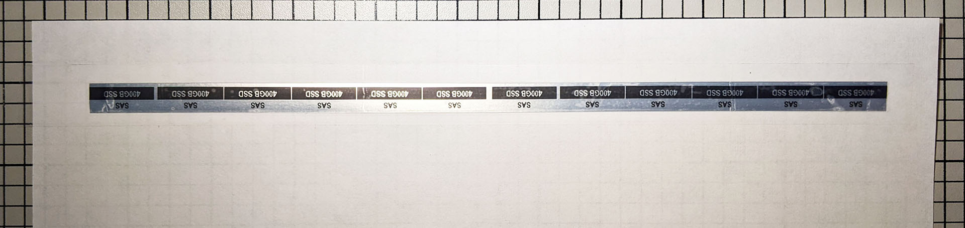
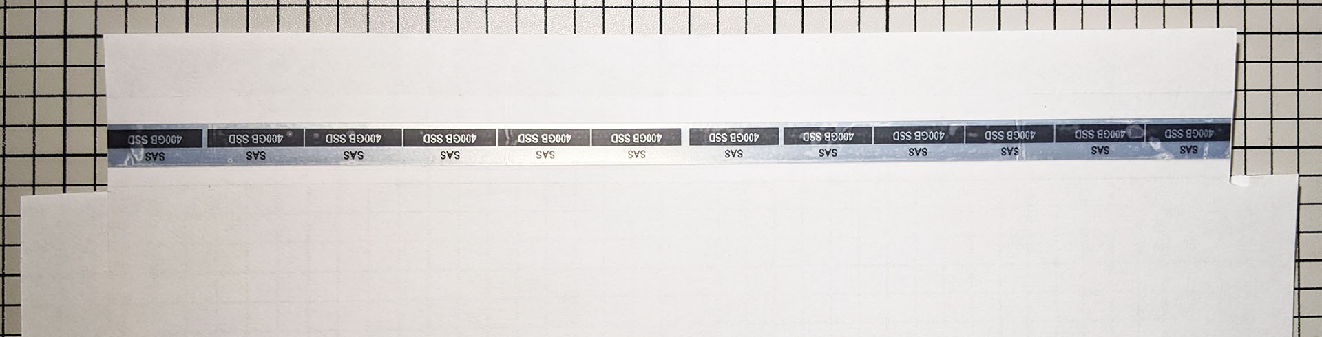
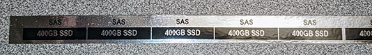
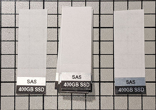
I then printed out the completed label strip. Note that the silver is more shiny and less matte than represented by the seller, but for $1.99 I can’t complain:
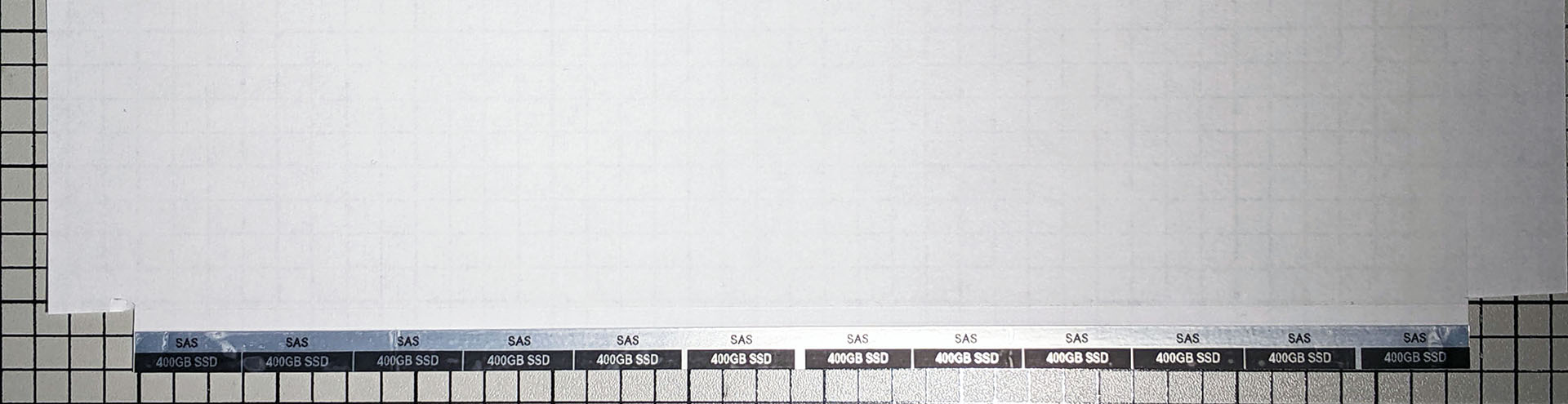
The next thing I did was tape the completed labels down to an 8.5 x 11 sheet of plain paper using 3/4″ Scotch “Magic Tape”. It is important to have the black stripe side of the labels closest to the edge of the paper and to center the tape on top of the label strip so that there is excess tape on all sides.
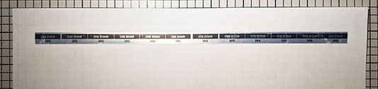
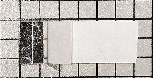
I then trimmed the sides of the paper so that the ends of the black stripe lined up with the cuts:
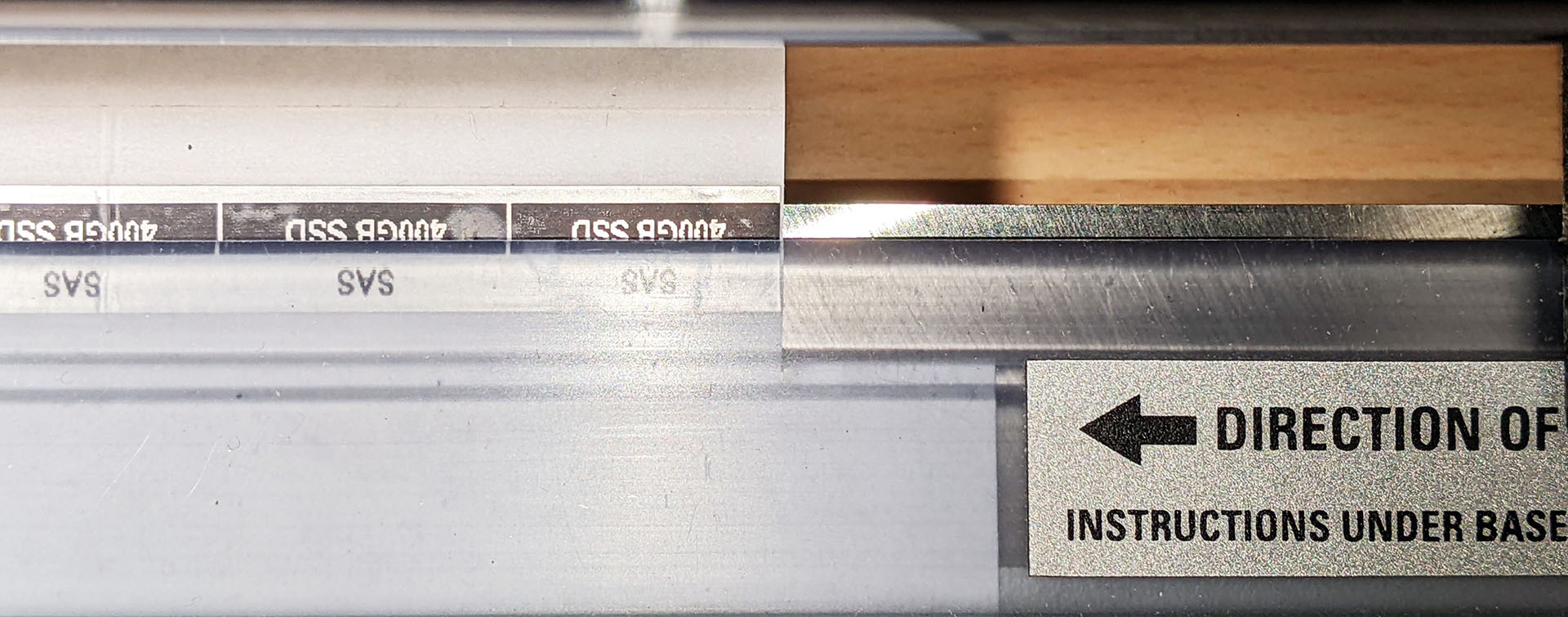
The previous step is necessary so the black stripe can be lined up exactly with the cutting path of the rotary trimmer:
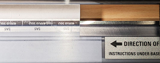
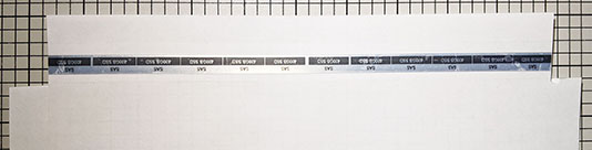
While holding the paper firmly in the correct position, I used the rotary trimmer to cut the label strip and remove the excess silver part from the long edge of the labels. This trimming is needed because the indent on the Dell drive tray is narrower than 9mm and the P-Touch printer cannot print all the way to the edge of the label. Trimming the labels solves both problems in one step:

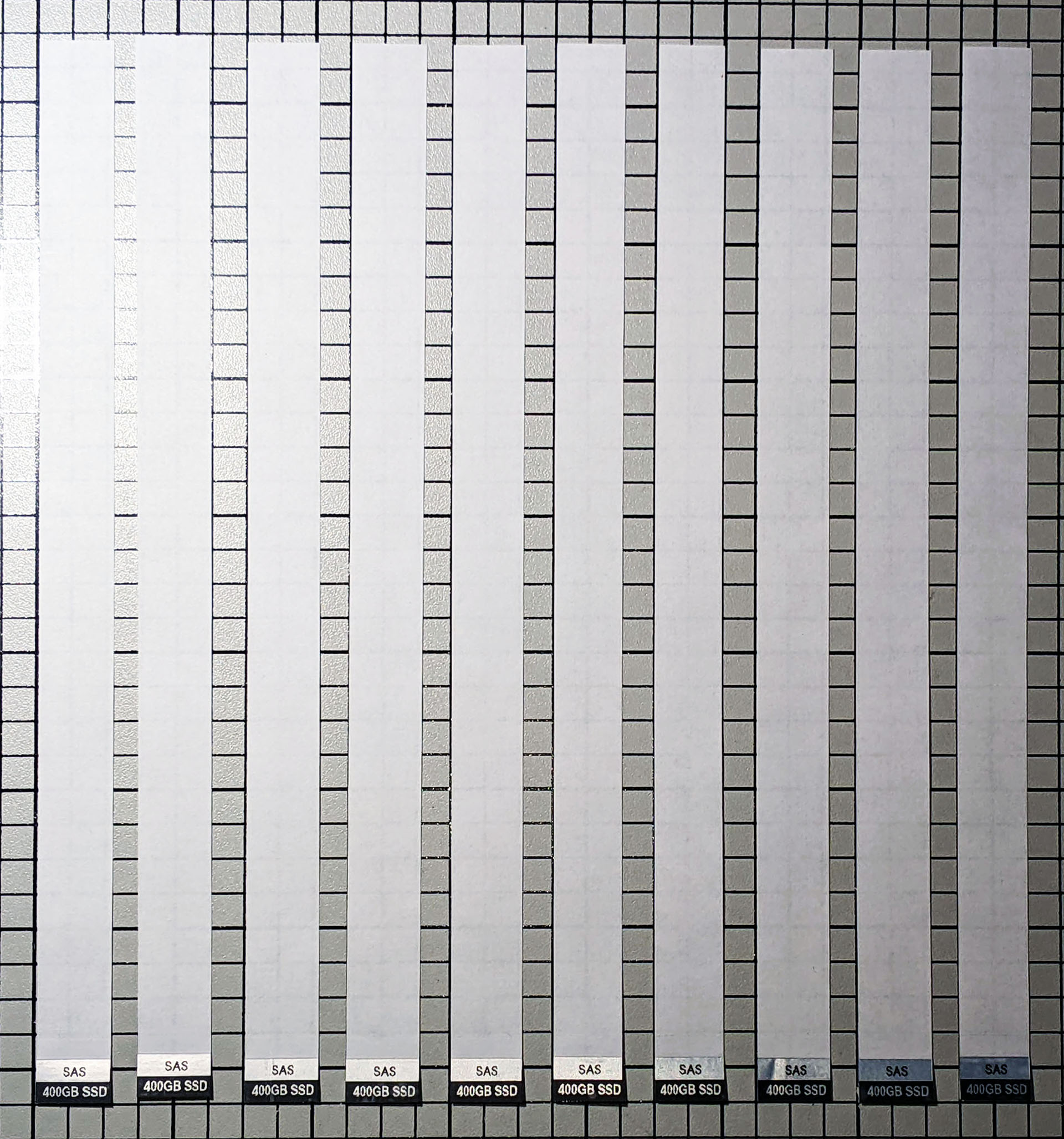
I then used the rotary trimmer to trim the sides of the labels to the correct width. This is something that requires practice – trim a label and hold it up to the drive tray and see if it is too narrow, too wide, or just right.
Next, I used scissors to cut off the excess paper ‘tails’ of each label:
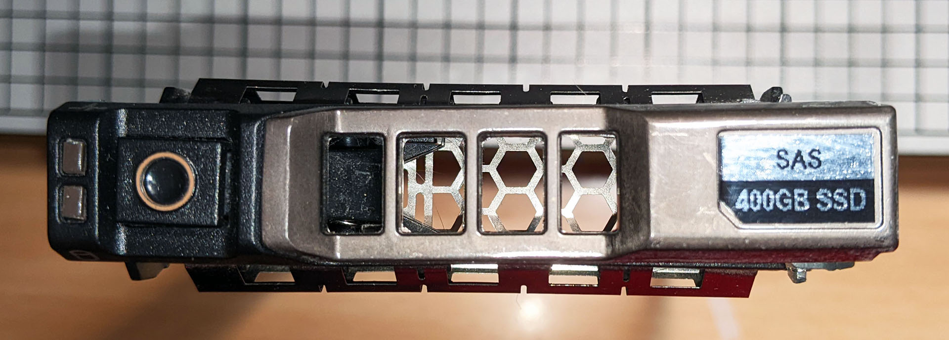
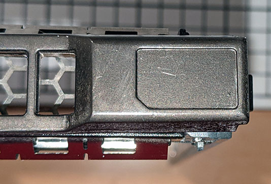
Here is the drive tray I’m going to apply a label to:
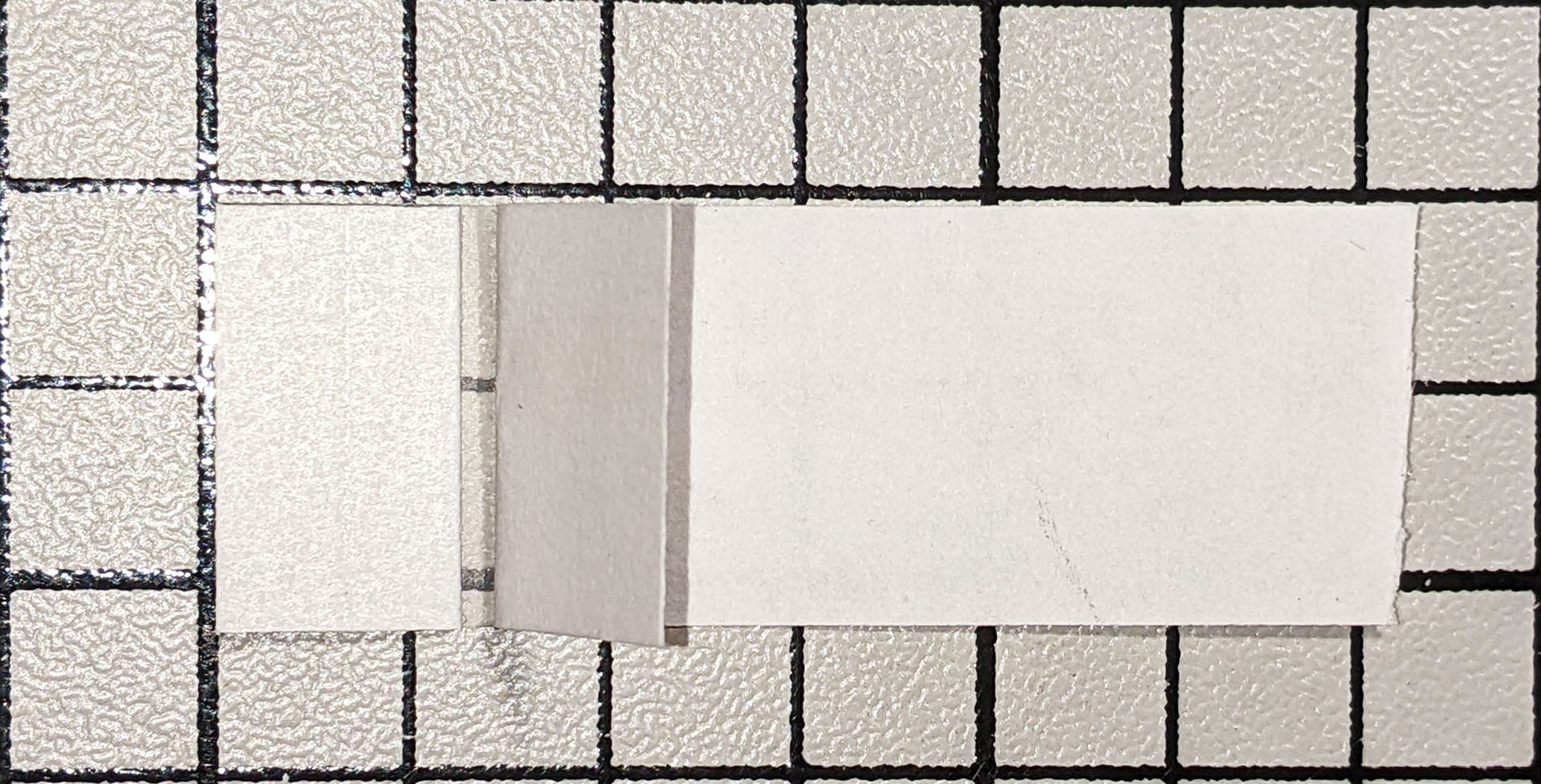
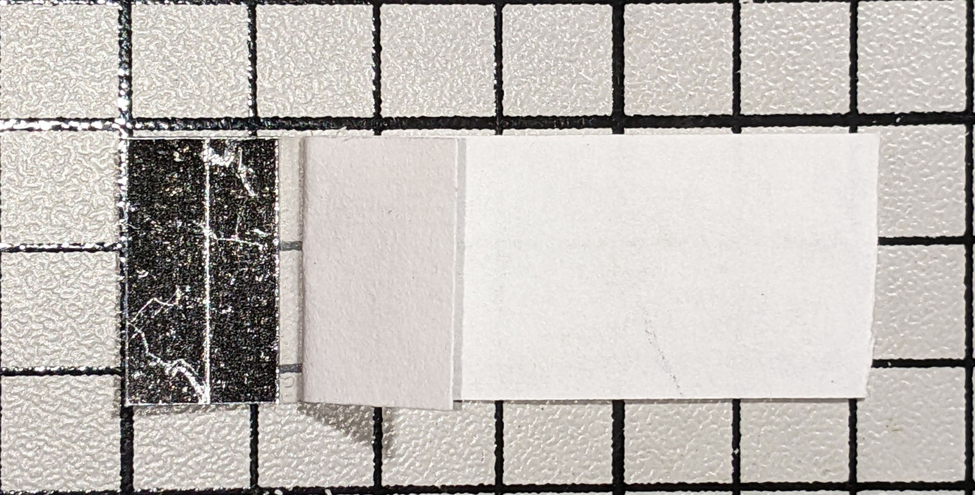
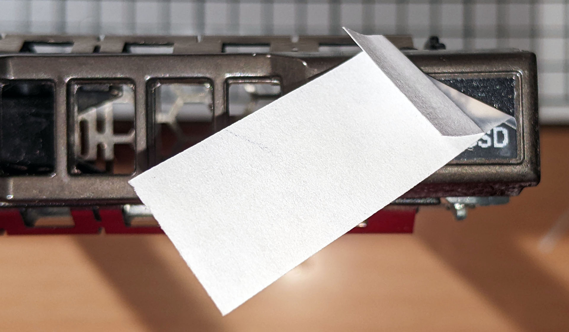
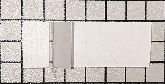
Peel back the paper and fold it over, leaving a short strip of tape exposed between the label and the paper:
Remove the wax paper backing from the adhesive side of the label. You may find a single-edge razor blade helpful:
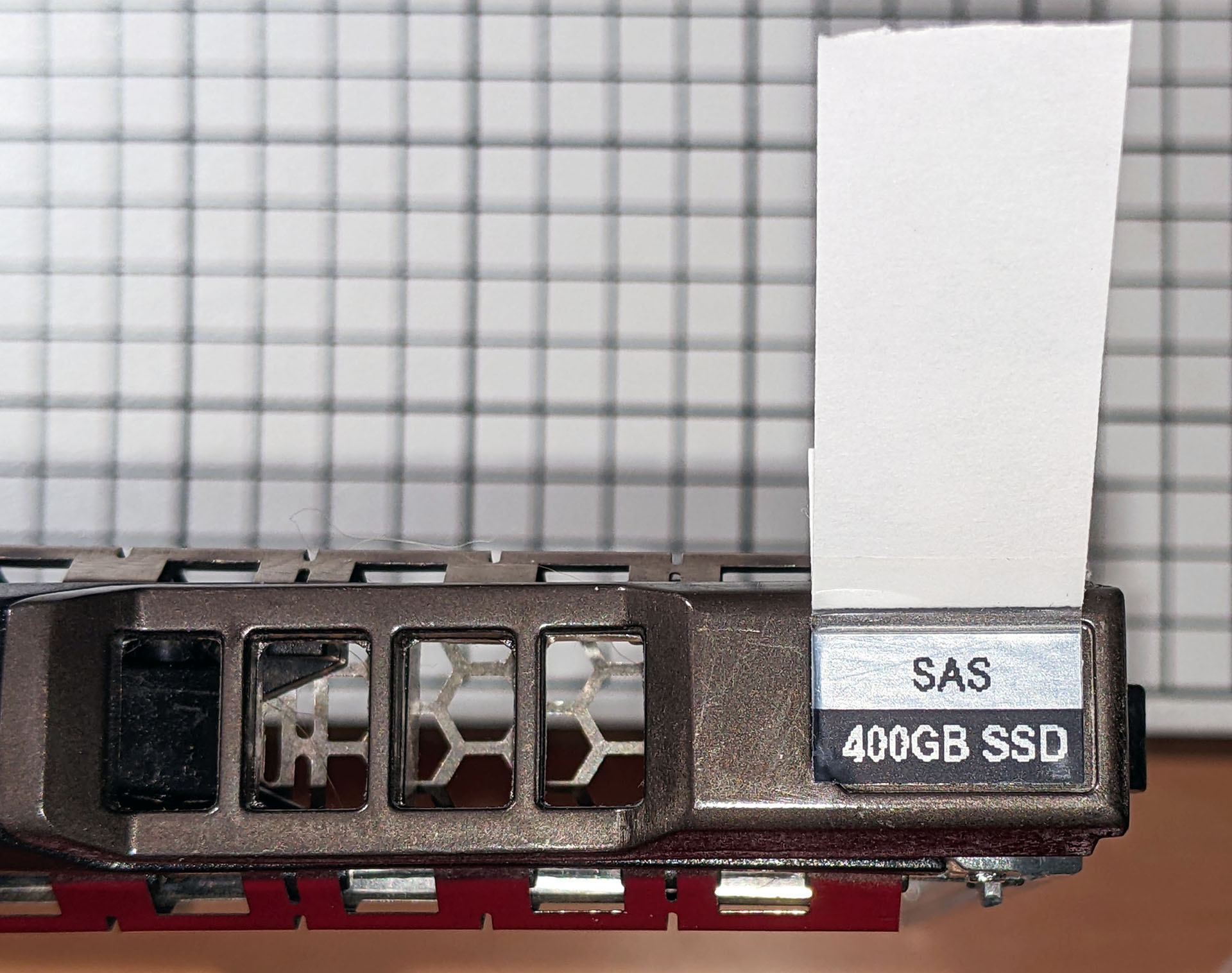
Carefully align the top, bottom and right sides of the label with the indent and apply the label, using the paper “tail” to hold and position the label:

Again using the paper “tail”, begin peeling the tape off the top of the label, starting at the top right. The adhesion of the label to the tray should be greater than that of the tape to the label, so the label should remain attached to the tray while peeling:

Continue removing the paper and tape until it is completely removed:
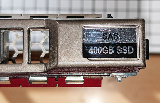
The left edge of the label needs to be pressed down into the tray indent. Then use a razor blade to cut the small diagonal notch on the bottom left of the label, taking care to not cut too deeply – you just want to cut the label, not the tray:

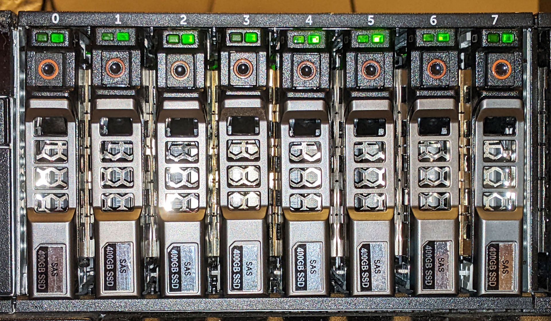
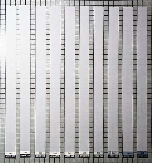
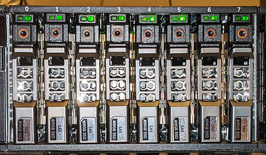
Repeat as needed until you have a system full of labeled trays:
You can use a similar method for 3.5″ drive tray labels or older generations of trays.