Reversing airflow on Cisco 3945 routers
The Cisco 3945 router ships with the default airflow “backwards” (back-to-front) compared with all other standard Cisco routers and switches. While back-to-front is available on a number of Cisco producta, as either a factory option (for example, the Catalyst 4948E-F) or as a field conversion (for example, the Catalyst 4500-X-16SFP), the 3945 is the only Cisco device I’ve encountered which defaults to a back-to-front airflow. There is an optional fan assembly (3900-FANASSY-NEBS) which has front-to-back airflow, but it is hard to find and represents a large additonal expense, since your 3945 presumably has a fan tray already that is working perfectly (but backwards).
This article shows how to convert a fan tray from the standard 3900-FANASSY to 3900-FANASSY-NEBS with the only new part required being an inexpensive (pennies) jumper and your time to do the conversion. NOTE: While it is possible to do this (with practice) by removing the fan assembly from a running 3945 and converting / reinstalling it before the 3945 shuts down from overheating, I suggest that you power down the 3945 first to avoid the problem. If you are converting multiple units, you can shuffle converted and un-converted fan assemblies with no downtime.
You will need the following tools and supplies:
- Small needlenose pliers
- Small diagonal cutters
- Phillips screwdriver
- Several small cable ties
- Fan mode jumper (more on this below)
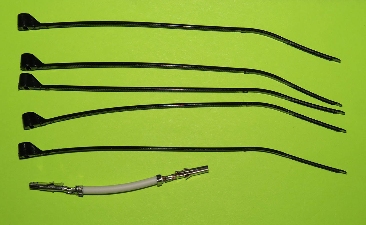
The “fan mode jumper” is just a short (1″ or so) length of wire with the correct pins on each end. The pins are Molex part number 39-00-0039, 18 cents each. The tool to crimp them is Molex part number 64016-0200, which is quite expensive at $137.21. However, you can get creative and use the small needlenose pliers to manually crimp the pin onto the cable. If you do this, I suggest also soldering the pin to the cable (after crimping) to ensure a good mechanical and electrical connection.
This is the jumper wire and the small cable ties (each picture is clickable to show a higher-resolution version):
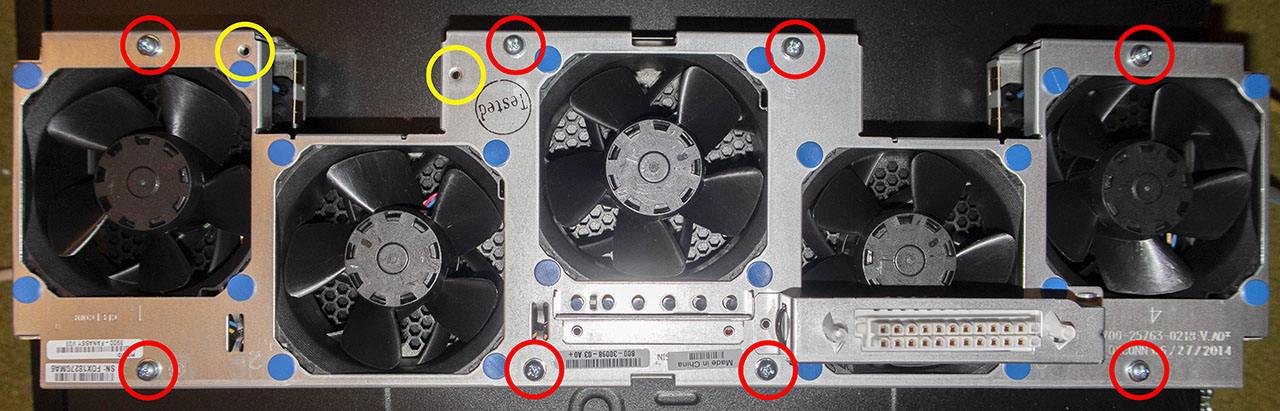
Following the Cisco instructions, remove the bezel and the fan assembly from the router. Place the fan assembly face-down on your work table and remove the 8 Phillips screws holding the two halves of the fan tray together, as indicated by the circled red areas in this picture. Your fan tray may or may not have screws in the circled yellow areas; you do not need to remove those. This is a new spare fan tray – your fan tray will likely be a lot dustier:
Carefully separate the two halves of the fan tray. One piece is only sheet metal – set that one aside for later. The other piece has the fans, wiring, and connector. That is the piece we will be working with. There is also a small clear plastic light pipe, as shown in this picture. Carefully remove it and set it aside for later:
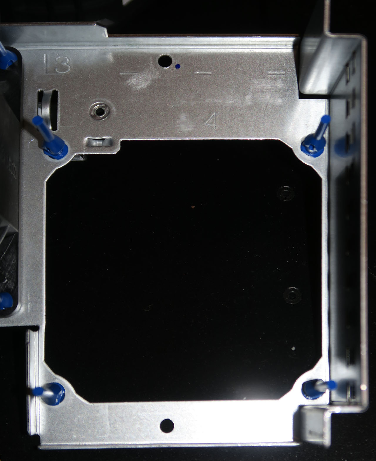
Each fan is held in place with 4 blue silicone rubber stakes. Here is a view of one of the fans:
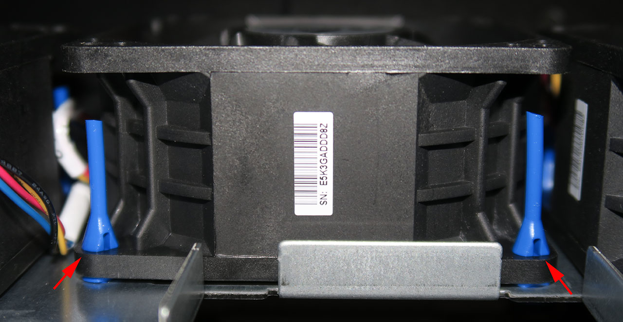
Starting with the rightmost fan (numbered 4 in the stampings on the tray), using the needlenose pliers, gently squeeze the expanding “V” part of the stake and carefully lift that corner of the fan up. Repeat with the 3 remaining corners of the fan and lift the fan out:
You may need to use the small diagonal cutters to cut a cable tie holding the fan wires in place if you don’t have enough slack to perform the next step. Flip the fan over so what was the top of the fan is now on the bottom (one side will have a part number sticker while the other side will be blank). Re-install the fan on the 4 blue silicone rubber stakes, and while gently pulling on the free “tail” of the stake, push the fan down against the metal of the fan tray until the expanding “V” part pulls through the fan. Repeat for each of the 4 remaining fans.
When you have the next-to-rightmost fan out, you will see the back of the connector that connects the fan tray to the router:
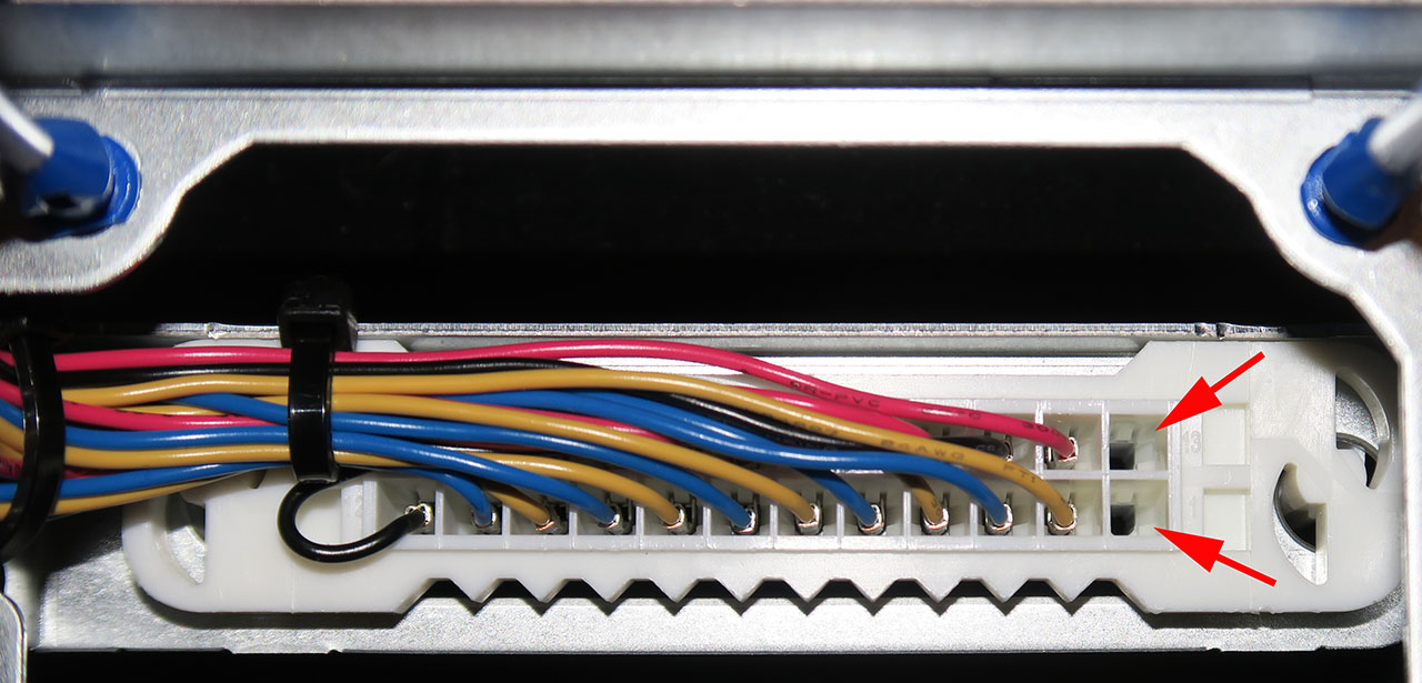
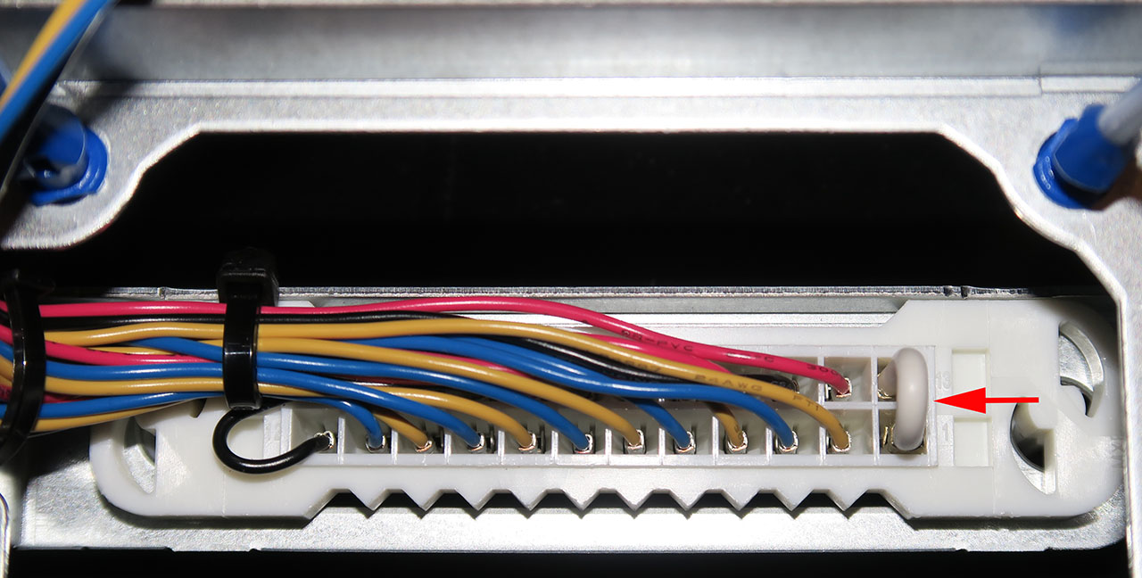
The red arrows in the previous picture show where the jumper needs to be installed. Bend the jumper into a “U” shape and carefully insert it into the connector until it clicks. You should end up with it looking like this:
Once you have all 5 fans flipped over, examine the underside of the fan tray to make sure there are no wires sticking out and that the fans are all fully seated on the blue silicone rubber stakes. An un-seated stake will generally appear slightly “popped out” when you look at the underside of the fan tray.
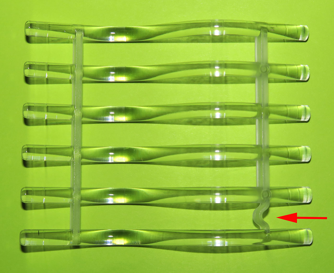
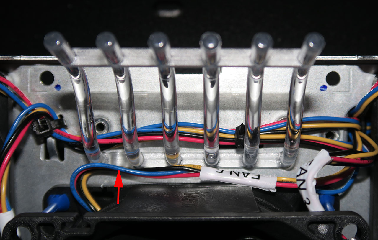
Use the small cables ties to replace any ties you had to cut to get enough slack to flip the fans over. Next, re-install the light pipe. The small U-shaped bend lines up with a matching protrusion on the sheet metal, shown with an arrow in this picture:
Carefully re-install the other sheet metal half of the fan tray that you set aside at the beginning. You may have to wiggle the light pipe a bit to get it to line up with the holes in the fan tray. Make sure that the two halves of the fan tray are fully seated on each other with no protruding pieces (there are interlocking metal tabs on the two halves). Also make sure that no wires are sticking out or being pinched. If all looks good, re-install the 8 Phillips screws. Give the fan tray another look-over to make sure everything is in place, then re-install it in the router and power up the router. Once the router has booted, use the “show environment all” command to verify that all 5 fans are operating correctly and that the router has detected the new jumper and is operating in front-to-back mode:
SYSTEM FAN STATUS
=================
 Fan Tray: Installed with Reverse Air Flow. Air Filter Supported.
 Fan 1 OK, Low speed setting
 Fan 2 OK, Low speed setting
 Fan 3 OK, Low speed setting
 Fan 4 OK, Low speed setting
 Fan 5 OK, Low speed setting
Technical minutiae: The only thing the jumper does is tell the router that a front-to-back airflow fan tray is installed. If you don’t install that jumper, the router will still operate with front-to-back airflow but the environmental readings will indicate that the unit is an “air conditioner” (exhaust air is cooler than intake air):
SYSTEM FAN STATUS
=================
 Fan 1 OK, Low speed setting
 Fan 2 OK, Low speed setting
 Fan 3 OK, Low speed setting
 Fan 4 OK, Low speed setting
 Fan 5 OK, Low speed setting

SYSTEM TEMPERATURE STATUS
=========================
 Intake Left temperature: 18 Celsius, Normal
 Intake Right temperature: 17 Celsius, Normal
 Exhaust Right temperature: 16 Celsius, Normal
 Exhaust Left temperature: 17 Celsius, Normal
 CPU temperature: 49 Celsius, Normal
 Power Supply Unit 1 temperature: 21 Celsius, Normal
 Power Supply Unit 2 temperature: 22 Celsius, Normal
As you can see, exhaust air is being reported as 1 degree cooler than entering air. This is because the router doesn’t know the airflow is reversed, so the sensors behind the fan tray are being treated as exhaust and the sensors by the rear I/O panel are being treated as intake. Installing the jumper lets the router know airflow is reversed and that it should report the rear I/O panel sensors as exhaust and the sensors behind the fan tray as intake:
SYSTEM FAN STATUS
=================
 Fan Tray: Installed with Reverse Air Flow. Air Filter Supported.
 Fan 1 OK, Low speed setting
 Fan 2 OK, Low speed setting
 Fan 3 OK, Low speed setting
 Fan 4 OK, Low speed setting
 Fan 5 OK, Low speed setting

SYSTEM TEMPERATURE STATUS
=========================
 Left Intake temperature: 20 Celsius,  Normal
 Right Intake temperature: 18 Celsius,  Normal
 Right Exhaust temperature: 20 Celsius,  Normal
 Left Exhaust temperature: 21 Celsius,  Normal
 CPU temperature: 61 Celsius, Normal
 Power Supply Unit 1 temperature: 23 Celsius, Normal
 Power Supply Unit 2 temperature: 25 Celsius, Normal
Note: the two “show environment all” reports above were performed at different times, thus the differing temperature readings. There is no difference in cooling efficiency when reversing the airflow direction.
