BMW offers lumbar (lower back, also known as lordosis) support as an E46 option outside the US. It is apparently possible to order it in the US (option code 488) if your dealer and BMWNA are both in a good mood and the planets are aligned properly. Update: lumbar support is now available in the US on custom ordered cars.
When I ordered my car, I was unaware of this, so I have a car without factory lumbar support. There is a BMW part number for a "Lumbar Retrofit Kit", but that part number (01 10 4 444 444) is just a place-holder. It doesn't exist, can't be ordered, and so on.
One of the members of Bimmerfest, JoeCinVa, did the research using an online TIS subscription to determine what was involved in retrofitting lumbar support. His information was what led me to conclude that a retrofit was possible. This DIY varies from his list of parts, probably because I was working from a newer parts catalog CD.
As usual with my DIYs, the reader is expected to be familiar with general BMW shop procedures and have appropriate documentation (Bentley manual, TIS, etc.) available for points not covered in detail in the DIY. Further, the parts list shown here are the parts I used for my 09/2002 build 325xiT sport wagon. Your vehicle may need different parts (particularly if it is an older build). As always, check with your parts vendor to make sure you are ordering the correct parts for your specific vehicle.
Important Note: This DIY is not for the squeamish - it involves a lot of patient poking, prodding, and so forth. I strongly suggest that you not attempt it as your first DIY.
You will need:
- 52 10 7 115 693 Qty. 2 - Lumbar support pump ($95.25)
- 52 10 7 160 372 Qty. 2 - Valve unit ($64.00)
- 52 10 8 099 007 Qty. 2 - Lordosis pad ($32.50)
- 52 10 8 226 401 Qty. 1 - Wiring for left seat (manual seats) ($70.75)
- 52 10 7 226 402 Qty. 1 - Wiring for right seat (manual seats) ($70.75)
- 52 10 8 226 403 Qty. 1 - Wiring for left seat (power seats) ($70.75)
- 52 10 7 226 404 Qty. 1 - Wiring for right seat (power seats) ($70.75)
- 61 31 8 352 291 Qty. 1 - Left lumbar support switch ($41.50)
- 61 31 8 360 877 Qty. 1 - Right lumbar support switch ($41.50)
- 52 10 8 240 495 Qty. 2 - Seat parts kit ($3.98)
- 07 11 9 902 007 Qty. 2 - M5 x 14 bolt (OK to use generic M5 bolt)
- Optional: 52 10 8 240 091 Qty. 1 - Black covering, left side ($8.50)
- Optional: 52 10 8 240 092 Qty. 1 - Black covering, right side ($8.50)
- Optional: 52 10 8 240 093 Qty. 1 - Gray covering, left side ($8.50)
- Optional: 52 10 8 240 094 Qty. 1 - Gray covering, right side ($8.50)
- Optional: 52 10 8 240 095 Qty. 1 - Beige covering, left side ($8.50)
- Optional: 52 10 8 240 096 Qty. 1 - Beige covering, right side ($8.50)
- Dremel or similar tool. I used the Dremel 194 cutting bit and the Dremel 439 mandrel and sanding band.
- T20 Torx driver
- Small screwdriver
- Diagonal cutters
- Needle-nose pliers
- Protective equipment (goggles, gloves, respirator, etc.) as required.
The above BMW prices are dealer list. You should be able to save a substantial amount of money by purchasing from one of the US mail-order dealers.
As always, verify the above part numbers apply to your particular VIN when ordering from the BMW parts counter.
I suggest the ... 240 495 seat parts kits as they aren't that expensive and you might need some of the other components of that kit if you break anything while removing the seat back. The actual pins that you'll be using from the kit are 52 20 1 964 201 and cost $0.42 each (you'd need 4).
The optional coverings are replacement pieces for the sides of the seat which surround the seat controls. As you will have to cut a hole in these pieces, I suggest purchasing a replacement set to work with instead of removing the original ones from your car at this stage.
Assembly instructions with pictures follow. Take your time and use protective equipment whenever you are cutting, grinding, sanding, or glueing.
Each of the images is clickable to display a higher-resolution version.
I strongly suggest that you purchase the optional side pieces of the appropriate color. Aside from not needing to take the car apart when making the holes for the lumbar switch, it is very useful to have the new pieces to use to determine where the clips are when trying to remove the old pieces from the car. Also, it is quite probable that you will break one or both of the old pieces when removing them.
The hardest part of the project is cutting the holes in the seat switch panels. There doesn't seem to be a way to order these panels with the hole already cut out (the plastic panel has some lettering on the inside which gives part numbers for the piece both with and without the hole, but those part numbers aren't valid BMW parts). So you have to carefully cut the holes yourself. Fortunately, the switch protrudes a bit and will cover minor mistakes.
![[The Dremel tool and bits]](6F5S2169-s.jpg)
This is the Dremel tool and bits that I used. The bit in the chuck is the 1/8" router bit that I will use for the initial cut, and the bit on the floor next to it is the sanding bit I will use for the final sanding.
![[Outside surface before cutting]](6F5S2165-s.jpg)
This is what the outer surface of the seat panel looks like before it is cut. The lumbar switch will be installed in the circular depression.
![[Inside surface before cutting]](6F5S2166-s.jpg)
Here you see the inside view of the same area. The 4 short tabs support the switch, while the two larger ones are the retaining clips for the switch. Pay attention to the slot on the right side of the circle - that is a keying slot and there is a matching tab on the switch. Don't get your left and right side switches confused!
![[Cut started on inside]](6F5S2171-s.jpg)
In this picture I have started cutting away at the plastic from the inside of the seat panel. Stay well inside the circle in case your tool slips. Make multiple passes, cutting away only a small thickness of material in each pass - otherwise it will build up in blobs of melted plastic and you'll have to cut through it again. Proceed until you have cut through the entire thickness of the plastic. As always, be sure to wear appropriate protective gear to avoid injury from the use of power tools.
![[Center removed]](6F5S2173-s.jpg)
This is the rough opening as viewed from the outside. The center plastic has been removed, but we need to sand the opening, which we'll do in the next step.
![[The finished hole from the outside]](6F5S2176-s.jpg)
Sand the opening, taking off only a slight amount of material in each pass. You want the hole to be even with the outer edge of the depressed area (removing the entire depressed area).
![[The finished hole from the inside]](6F5S2177-s.jpg)
Looking at the hole from the inside, make sure that you have sanded off any protruding plastic - the hole should be smooth and even with the lip on the inside. The hole isn't perpendicular to the trim piece - it is on a slight angle, so it is possible to have a smooth-looking hole on the outside but have protruding parts on the inside, which will cause the switch to bind when it is installed.
![[Switch installed from outside]](6F5S2178-s.jpg)
Once you're happy with the hole, snap the switch into place after making sure that you have the right switch and the key on the switch is lined up with the notch on the inside lip of the hole. Press each of the 4 arrows to make sure the switch doesn't bind when operating.
![[Switch installed from inside]](6F5S2179-s.jpg)
Here is a view of the switch mounted on the inside. Note that it is difficult to remove the switch once it is installed, so make sure you have things trimmed and sanded properly before snapping it into place.
Now, do the same for the other side piece.
![[The wrong connector on the 401/402 harness]](6F5S2407-s.jpg)
I believed the 09/2003 ETK, which said I needed the 401/402 harnesses for a car with power seats with memory. Silly me - apparently the 403/404 harnesses are needed in this case. I decided that I didn't want to wait another 2 weeks for the 403/404 harnesses to arrive from Germany, so I modified the 401/402 ones. You shouldn't have to do these steps (assuming that the 403/404 harnesses are actually correct).
This picture shows the incorrect connector on the 401/402 harnesses.
Important Note: Apparently these were the right connectors - they just plug in somewhere I couldn't see without removing the seats from the car. Stay tuned for updated information once I investigate further.
UPDATE: 401/402 are for manual seats. You will probably need to obtain the matching pins for the connector body that's already under the seats and run power to somewhere in the car. 403/404 are for power seats, either with or without the memory option. Updated pictures will be posted later.
![[61 13 0 005 201 pin]](6F5S2408-s.jpg)
This is the 61 13 0 005 201 pin (which BMW calls a "Bushing Contact") which mates with the connector on the seat controller.
![[Heat shrink tubing for pin]](6F5S2409-s.jpg)
Unfortunately, I didn't have the connector housing for these pins, so I decided to put some heat shrink tubing over the pins and just stick them into the connector. This is the tubing next to the pin, before shrinking.
![[Tubing shrunk on pin]](6F5S2410-s.jpg)
Here I've shrunk the tubing over the pin. I repeated the process for the second pin.
![[The modified cable]](6F5S2411-s.jpg)
This is the modified cable. I've cut off the incorrect connector, soldered on the new pins, and then used more heat shrink tubing to insulate the solder connection. Now, back to the project...
![[Location of Torx screw]](6F5S2412-s.jpg)
Refer to RA 52 16 040 from the TIS for information on how to remove the cover from the seat controls. It helps if you put the seat all the way forward, tilt the seat back as far forward as possible, and raise the seat most of the way. Again, it is very useful to refer to your new cover piece to see where the clips are. Removing this piece is a bit of trial-and-error, unfortunately. Start by using the T20 Torx driver to remove the screw from the hole shown in the photograph.
![[View of cut clip]](6F5S2415-s.jpg)
Now, refer to RA 52 15 198 from the TIS for instructions on removing the seat back. Unless you have a very unusual set of diagonal cutters, you will need to use a small screwdriver to bend the head of each clip in order to get the cutters under it. Once you have bent the clip head, cut the head off the clip with the cutters. After cutting both clips, gently pull the bottom of the rear panel about an inch away from the seat and slide the panel down to remove it. You will now see the remainder of the clip as shown in this picture. Remove both cut clips and discard them.
![[Picture of cut clips]](6F5S2416-s.jpg)
Here you can see the two clips after they have been cut and removed.
![[Lumbar switch wiring]](6F5S2417-s.jpg)
Insert the wiring harness for the lumbar switch into the slots on the cover panel as shown in the photograph. It is very important that you seat the wire fully into the slots or the cover panel will not go back on properly.
![[Seat control module]](6F5S2418-s.jpg)
Now, insert the seat control module into the new side piece. Make sure it engages with the tabs and clips.
![[Lumbar harness power connection]](6F5S2419-s.jpg)
Next, insert the lumbar wiring harness power connector into the side of the seat controller module. Note: if you have the correct harness, your connector will look somewhat different.
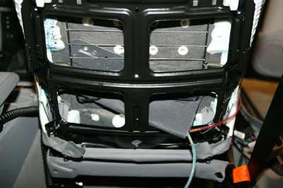
![[View of opened seat back]](6F5S2420-s.jpg)
This is what the inside of the seat back will look like once you have removed the cover (which you did a few steps back). Take careful note of the size of the lower right rectangular opening...
![[This goes where???]](6F5S2422-s.jpg)
Now you have to carefully insert the lumbar support pad into the seat back. Remember that small rectangular hole in the previous photograph? That's where you need to insert it. Refer to RA 52 13 050 from the TIS for additional information.
I folded the pad in half to slide it through the opening. Once inside, I started working it up behind the seat back springs. Once I had it positioned as shown in this photo, I unfolded it back to its original size. Be very careful, as the plastic of the pad isn't very tough and it is also easy to damage the pad where the hoses attach. Also, be careful as the black metal part of the seat has very sharp edges and it is quite easy to cut your hands on it.
![[Pad installed]](6F5S2424-s.jpg)
After a substantial amount of fiddling around, I have the pad in place. Note that the one large and two small tabs on the top of the pad are hooked around one of the support wires. Again, refer to RA 52 13 050 from the TIS for additional information.
![[Hole for 5mm bolt]](6F5S2426-s.jpg)
This picture shows the area where the valve will be installed. Install a 5mm bolt through the hole. The head of the bolt stays inside the seat, while the threads stick out through the hole.
![[Bolt installed]](6F5S2427-s.jpg)
Here the bolt has been installed. Note that you can't use a screw - it has to be a hex-head bolt so you can get a wrench on the head to tighten it in a subsequent step.
![[Valve installed]](6F5S2428-s.jpg)
Place the valve assembly in the depression to the left of the bolt. Carefully reach into the seat and hand-tighten the bolt. Continue tightening with a wrench until the valve assembly is securely attached.
![[Connecting the hoses]](6F5S2429-s.jpg)
Carefully route the red and blue hoses from the lumbar pad through the hole in the metal frame to the right of the valve assembly. Be careful to avoid kinking the hoses. Remove both the white shipping cap from the three brass fittings and the black shipping cap from the exhaust port of the valve. (If you forget to remove the black cap, you will be unable to deflate the pad). Connect the red and blue hoses to the valve, making sure to match up the colors with the marks on the valve.
![[Installing the pump]](6F5S2430-s.jpg)
Test-fit the lumbar pump on the right rear of the seat frame, across from the valve. Make sure you can seat it fully. You may need to carefully move a wire if you have heated seats (that is the wire in this picture). Once you have determined where the pump will go, remove the wax paper from the sticky tape and attach the pump to the seat frame.
![[Connecting the pump and wiring]](6F5S2432-s.jpg)
Connect the pump hose to the valve assembly. Follow the same route into the seat back that the seat heater wire takes, and connect the pump and valve to the wiring harness.
![[Storing the slack in the wiring]](6F5S2433-s.jpg)
You will likely have a lot of slack in the wiring. Feed it through the same hole in the seat back as the tubing and neatly tuck it into the back of the seat.
Now, test the function of the lumbar support before putting the seat back together. The function of the switch is not documented in detail in the owner's manual - pushing the top inflates the upper pad only, pushing the bottom inflates the lower pad only, pushing the front inflates both pads, and pushing the back deflates both pads.
If you have proper functionality, carefully reassemble the seat using the same instructions from the TIS you used to disassemble the seat. If the pad won't deflate, make sure that you removed the black shipping plug from the valve.
Use the replacement clips from the 495 kit to re-attach the seat back. That kit also contains the other pins and guides for the seat back, in case you damaged the originals while removing the back.
![[Lumbar wiring diagram]](lumbar1-s.jpg)
This is the wiring diagram for the lumbar option. Courtesy of JoeCinVa.
![[Lumbar connector pinouts and seat control]](lumbar2-s.jpg)
Here is the pinout of the control switch and a view of the installed switch. Courtesy of JoeCinVa.
![[Components in seat backrest]](lumbar3-s.jpg)
This picture shows the installed components in the backrest of the seat. Courtesy of JoeCinVa.
![[The Dremel tool and bits]](6F5S2169-l.jpg)
![[Outside surface before cutting]](6F5S2165-l.jpg)
![[Inside surface before cutting]](6F5S2166-l.jpg)
![[Cut started on inside]](6F5S2171-l.jpg)
![[Center removed]](6F5S2173-l.jpg)
![[The finished hole from the outside]](6F5S2176-l.jpg)
![[The finished hole from the inside]](6F5S2177-l.jpg)
![[Switch installed from outside]](6F5S2178-l.jpg)
![[Switch installed from inside]](6F5S2179-l.jpg)
![[The wrong connector on the 401/402 harness]](6F5S2407-l.jpg)
![[61 13 0 005 201 pin]](6F5S2408-l.jpg)
![[Heat shrink tubing for pin]](6F5S2409-l.jpg)
![[Tubing shrunk on pin]](6F5S2410-l.jpg)
![[The modified cable]](6F5S2411-l.jpg)
![[Location of Torx screw]](6F5S2412-l.jpg)
![[View of cut clip]](6F5S2415-l.jpg)
![[Picture of cut clips]](6F5S2416-l.jpg)
![[Lumbar switch wiring]](6F5S2417-l.jpg)
![[Seat control module]](6F5S2418-l.jpg)
![[Lumbar harness power connection]](6F5S2419-l.jpg)
![[View of opened seat back]](6F5S2420-l.jpg)
![[This goes where???]](6F5S2422-l.jpg)

![[Pad installed]](6F5S2424-l.jpg)
![[Hole for 5mm bolt]](6F5S2426-l.jpg)
![[Bolt installed]](6F5S2427-l.jpg)
![[Valve installed]](6F5S2428-l.jpg)
![[Connecting the hoses]](6F5S2429-l.jpg)
![[Installing the pump]](6F5S2430-l.jpg)
![[Connecting the pump and wiring]](6F5S2432-l.jpg)
![[Storing the slack in the wiring]](6F5S2433-l.jpg)
![[Lumbar wiring diagram]](lumbar1-l.jpg)
![[Lumbar connector pinouts and seat control]](lumbar2-l.jpg)
![[Components in seat backrest]](lumbar3-l.jpg)