Server pictures from March, 2018
This page has some pictures of the server racks as of March,
2018. Older pictures from 2005 can be found here, pictures from 2003
can be found here,
and pictures from 2000 can be found here.
Since I've received many requests saying "so, what does all this
stuff
look like?", I decided to take some quick pictures to show you. Each of
the following pictures is clickable to display an image twice as large. And
yes, all of this stuff is really in my house...
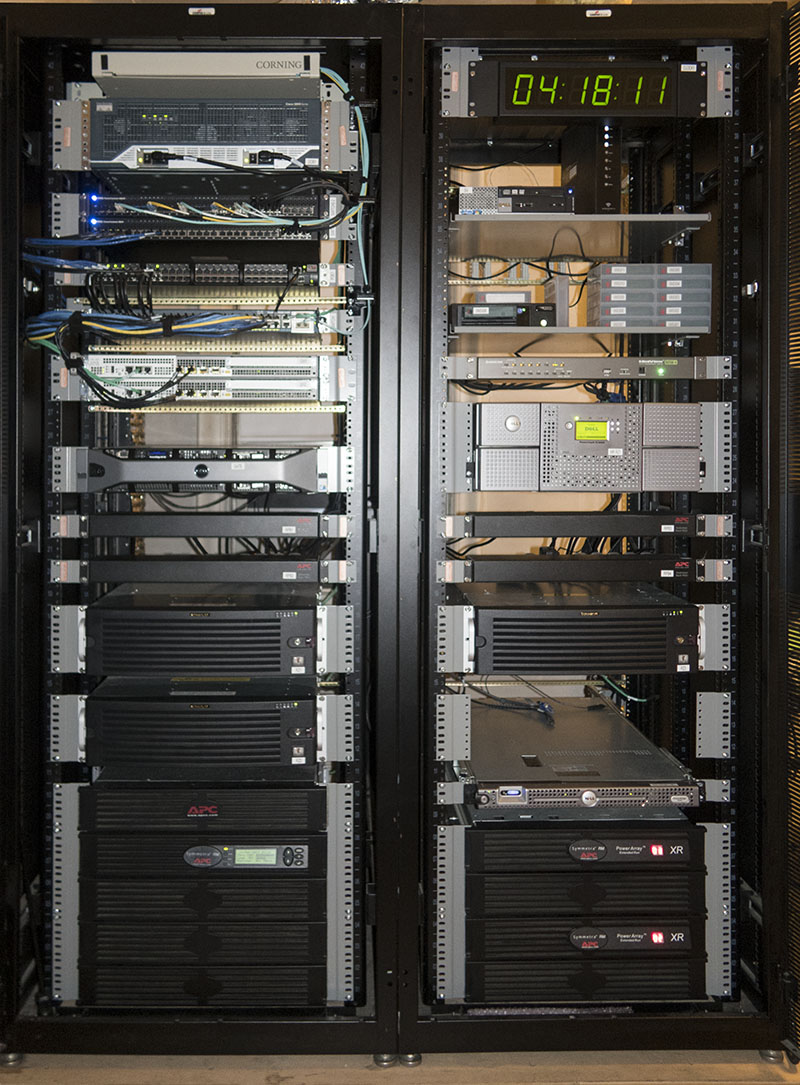
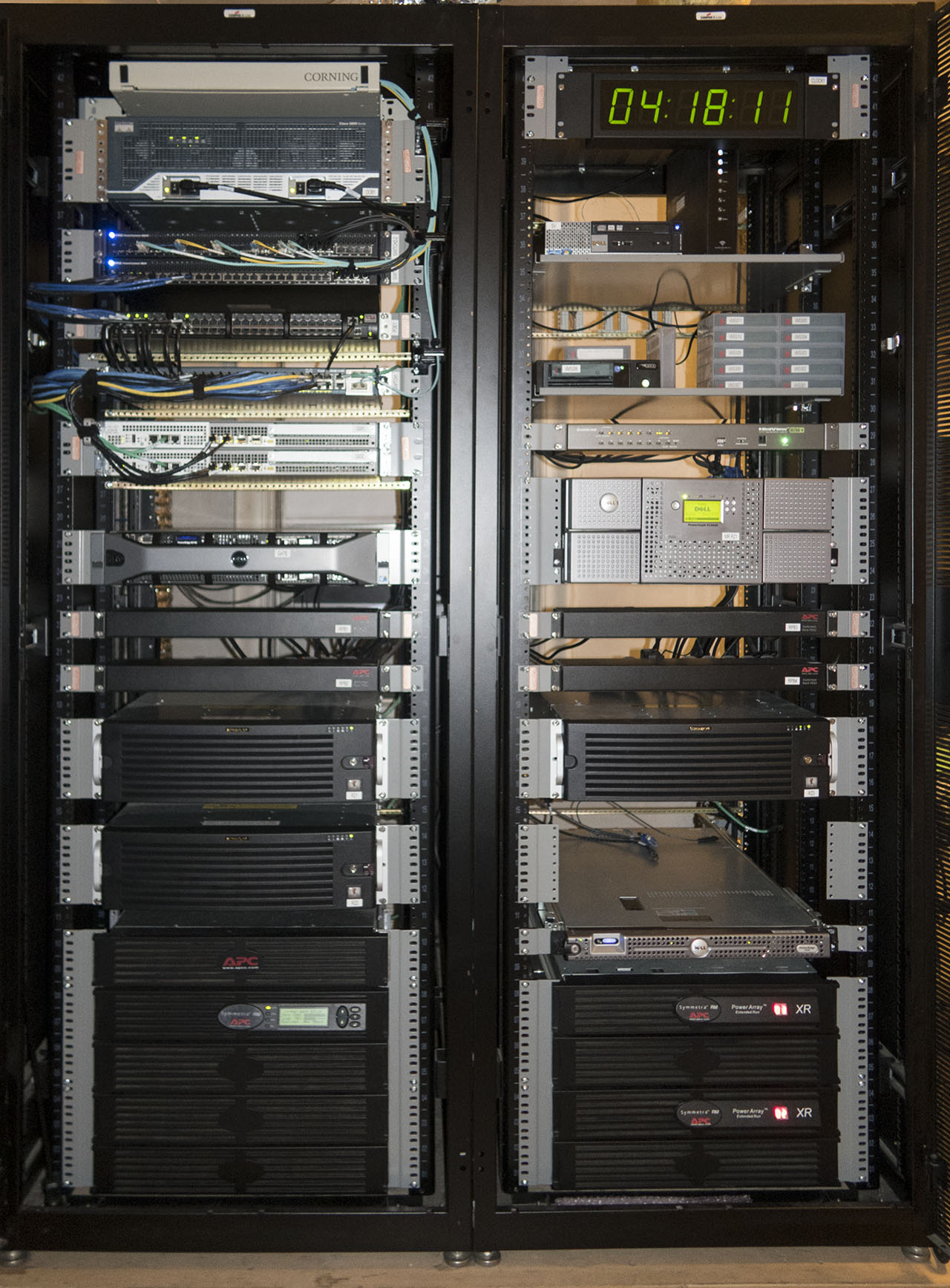
This is the overall view of the racks. In 2014 I upgraded from a
single rack (plus equipment stacked in piles on the floor) to a pair of
racks. I'll go into details about each piece of equipment further down this
page. The racks are 23" wide ("telco" spec) rather than the more common 19".
That is why there are grey metal "reducers" on each piece of equipment. The
extra 2" on each side gives me more room to run cables and reach inside the
rack when I need to. This is also the reason I leave a 1RU (rack unit) gap
between equipment - also, it helps when sliding equipment in and out if there
isn't a large pile of other equipment pressing down on it. There are three
pairs of rails in each rack - one set in the front, one set in the back, and
a third set in between them. The third set supports equipment that isn't deep
enough to reach to the back set of rails. The gold-colored bars you see under
some equipment are on those middle rails. There are mesh doors on the front of
the racks which were opened for these pictures. The back of the racks is
open, without doors, as the equipment is in my house and I'm not worried about
random people poking around in the back.
If you're very observant, you might have noticed that the racks are
sitting on a platform with a plywood top. Because the loaded racks weigh about
1500 pounds (the UPS equipment alone is 750 pounds), I needed to distribute the
weight across a larger area of the floor. There are 5 4x4's running at 90
degree angles to the floor joists, and then 2 layers of 3/4" plywood on top of
that. Not visible on top of the racks is a Cisco Aironet 702i wireless access
point (there are 3 more throughout my property).
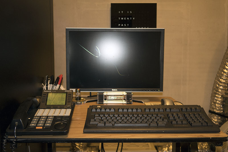
This is my work table immediately to the right of the racks. It has
a 24" monitor, keyboard and mouse (all hooked up to a KVM switch in the racks)
as well as a telephone. That isn't a giant scratch on the monitor - it is a
twisting "ribbon" from Microsoft's Mystify screen saver. You can also see 3 of
my collection of esoteric clocks. On the wall behind the monitor is a QLOCKTWO "word" clock. I had the first one
of these in the United States, although this one is a replacement as the
original one "lost its marbles" a few years ago and started randomly resetting.
Below the monitor is an IV-18 clock from Nixie Clock House. Behind the phone
you can see a "Dekatron DoHickie" from
Tortugascuba. While not technically a clock, it could be configured to
display time. The corrugated silver hose at the extreme right of the photo is a
cold air line, used to deliver cooling to the racks during warmer months.
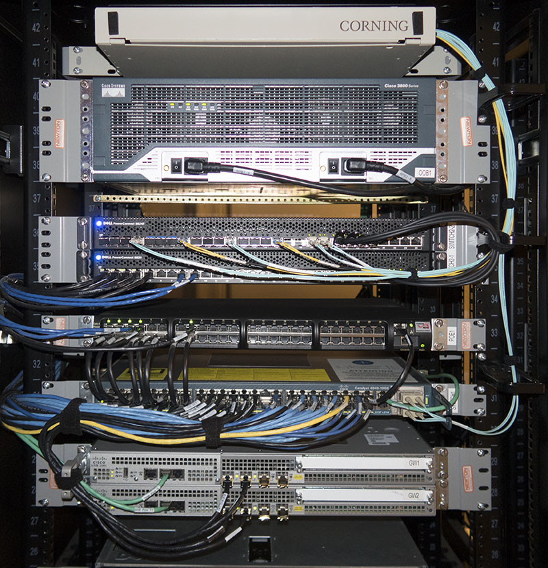
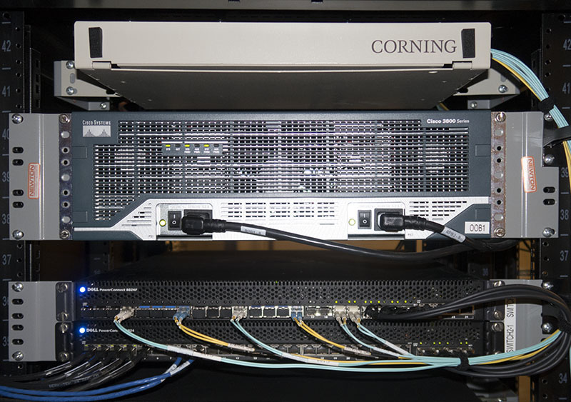
This is the top half of the left rack, which holds various
networking equipment. From the top down are:
- Fiber patch panel. 12 strands of fiber to one of my former off-site backup
locations terminate in this panel. While that fiber is no longer in use, the
patch panel provides a nice place to neatly coil up excess fiber.
- Cisco 3845 router. Its primary purpose is to provide out-of-band serial
connectivity (hence the "OOB1" label) to other equipment in this rack via a
NM-16A card. A secondary function is 14 VoIP termination ports using an
EVM-HD-8FXS/DID card with an EM-HDA-6FXO expansion module. Right now I am only
using 4 of the 14 ports. Also included are an NME-AIR-WLC8-K9 wireless LAN
controller card and an NME-NAM-120S network analysis module. Rounding things
out are 4 T1 ports (no longer in use) on a pair of VWIC-2MFT-T1-DI cards, a VPN
module and a compression module. Before I upgraded to dual ASR1001 routers,
this unit was my primary gateway.
- Dell PowerConnect 8024F and 8024 10 Gigabit Ethernet switches. These are
stacked via 4 DAC cables, which you can see on the right hand side of the
switches. This switch stack is trunked to the Catalyst 4948-10GE below via a
pair of multimode fiber links for a total capacity of 20Gbit/sec. VLANs are
used to keep traffic separated into griups. This leaves 38 ports for connecting
various pieces of equipment. Most ports are available for future use - at
present, the only 10 Gigabit links to end systems are the 4 RAIDzillas and the
Dell PowerEdge R710 (both described below). At some point I will extend the 10
Gigabit network to other locations in the house.
- PowerDsine PD-9024G/ACDC/M/F PoE (Power over Ethernet) injector. This is a
device which is inserted between a network switch and client devices to power
them over the Ethernet (rather than using "wall wart" power bricks). While this
is a 24-port unit, I have only cabled 8 ports to the Catalyst 4948-10GE below.
The first 4 ports provide power to four Cisco Aironet 702i access points, while
the 8th port powers the clock in the rack to the right. This is the managed
version of the unit, so it also has its own Ethernet connection to the Catalyst
4948-10GE (you can see this cable on the right). Using the management interface
I can remotely control power to each connected device as well as perform other
management tasks. This is a Gigabit Ethernet unit and can provide 36W of power
to each of the 24 connected devices.
- Cisco Catalyst 4948-10GE switch. This is my core network switch. It is
connected to the Dell PowerConnect switches above via a pair of 10 Gigabit
Ethernet multimode fiber links. It also connects to 3 other Catalyst 4948 switches
throughout the property, via Gigabit Ethernet (the 10 Gigabit Ethernet is only
used within these racks). The cables are color-coded - black is for network
cables within the racks, blue is for network cables that go outside of the
racks, green is for the serial console and yellow is for special purposes
(this one connects to the Network Analysis Module in the Cisco 3845 router
above).
- A pair of Cisco ASR1001 routers. These connect my equipment to the outside
world via Gigabit Ethernet and a 100Mbit/sec backup Ethernet. They are both
trunked to the Catalyst 4948-10GE via a pair of Gigabit Ethernet cables. Those
cables carry a half dozen or so VLANs. The routers use HSRP for redundancy, so
either can fail (or be reloaded) without affecting connectivity.
The cabling is supported and organized with both Velcro ties and vertical cable
management rings, visible on the right-hand side of this picture. Each cable
has a "self-laminating" printed label (printed with a Brady TLS2200 label
printer) identifying where it goes and what it is used for. Each piece of
equipment is also labeled with its name (printed on a Brother P-Touch PC label
printer).
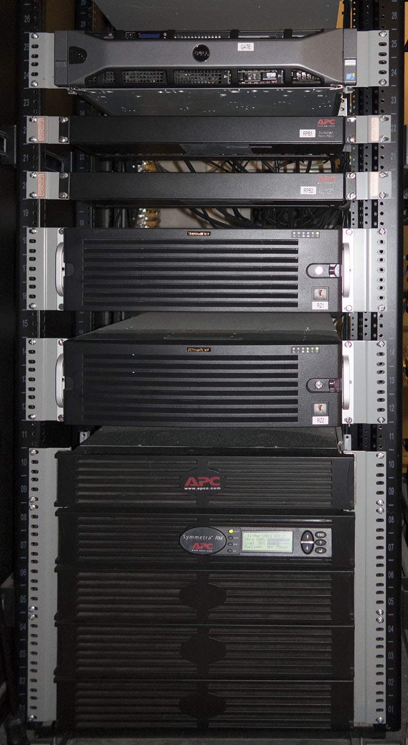
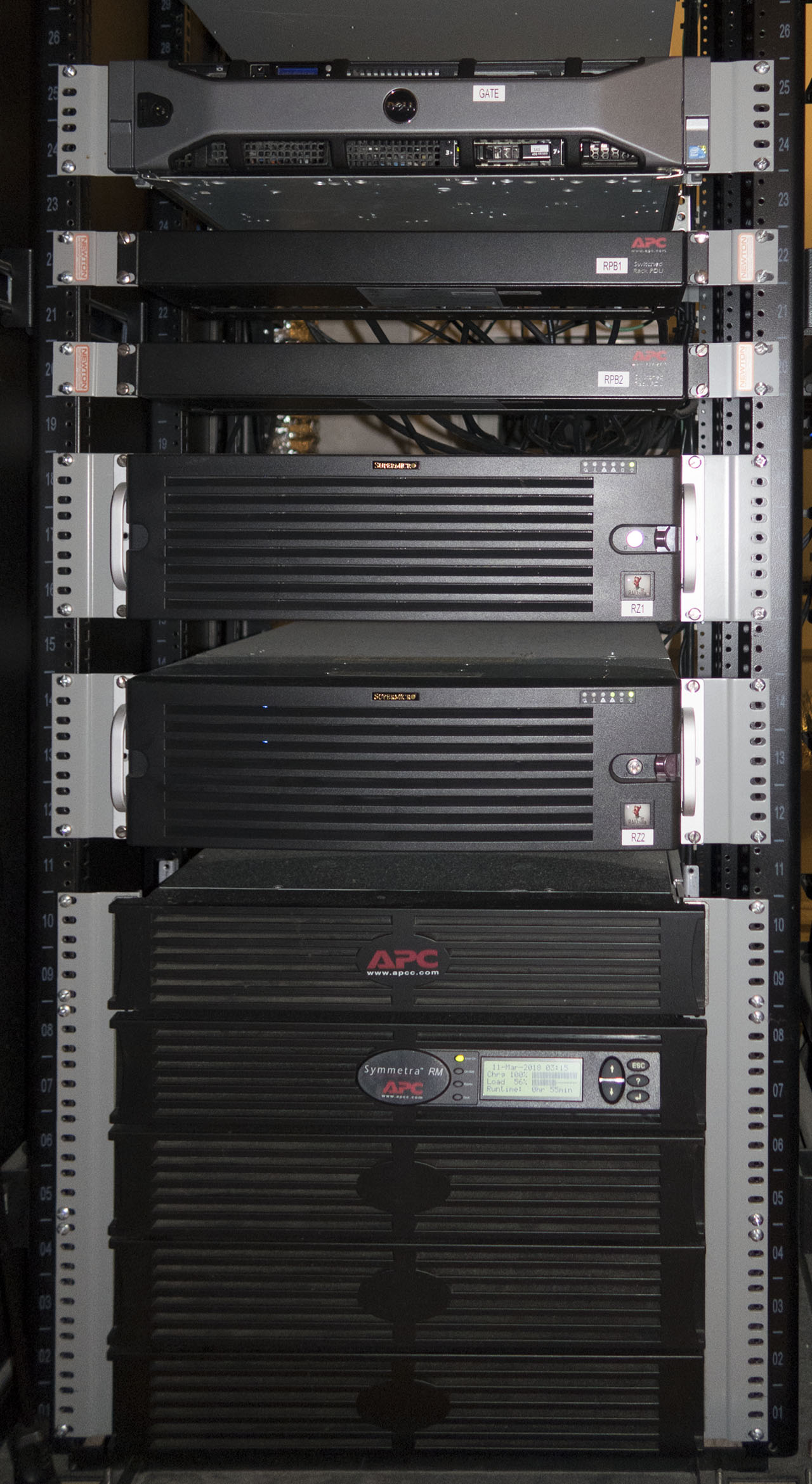
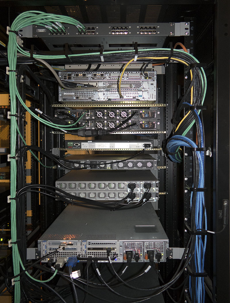
This is the bottom half of the left rack, which holds various
servers as well as power management and UPS equipment. From the top down are:
- Dell PowerEdge R710 server. This is the system that is serving this page to
you, as well as providing many other services (for example, it is ftp.infozip.org). It has dual Xeon X5680 CPUs,
48GB of RAM, and 4 400GB SAS solid state drives (SSDs). It connects to the rest
of the equipment via 10 Gigabit Ethernet. It also has an LTO4 tape drive
(located in the rack to the right) which is used for backing up various
virtual machines hosted on this system.
- A pair of APC AP7900 switched and metered power distribution units (PDUs).
These let me remotely power-cycle any of the equipment in this rack, and also
monitor the power consumption.
- A pair of RAIDzilla 2.5 servers. Each holds
128TB of disk storage and has 96GB of RAM. They connect to the rest of the
equipment via 10 Gigabit Ethernet, and are mirrored to off-site units for data
protection. These connect to a LTO6 tape library in the rack to the right,
which is used for making scheduled tape backups.
- APC Symmetra RM UPS. This is a modular 6KVA unit. Two expansion chassis are
located in the rack to the right, which provide an additional 8 battery
packs for a total run-time of over 2 hours. At the top of the UPS is an APC
SYTF2 transformer (for some reason, this UPS only produces 208V output and
needs a transformer to step that down to 120V).

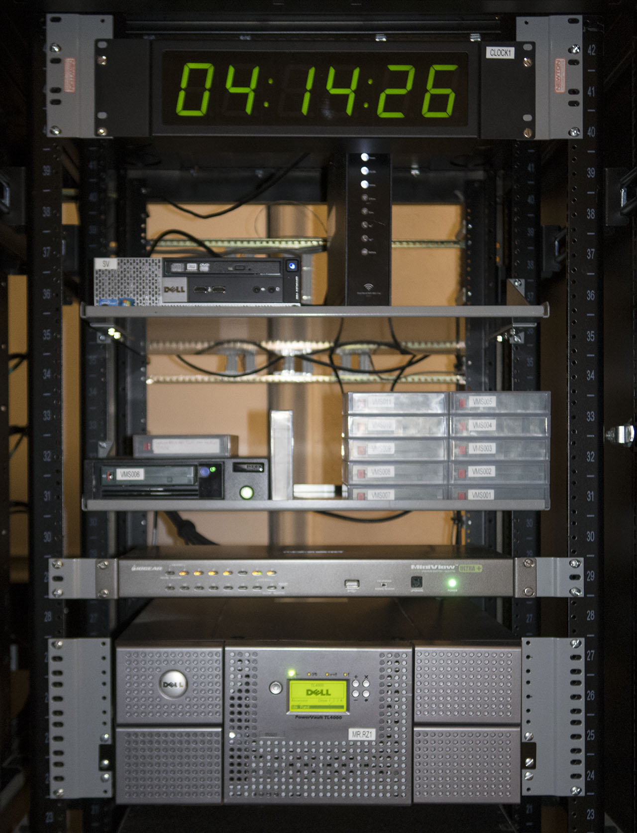
This is the top half of the right rack. From the top down are:
- Clock from Time Machines.
This clock is synchronized using NTP (Network Time Protocol), so it shows the
same exact time as my servers and other equipment. It is powered over Ethernet
via the PoE injector in the left-hand rack. Yes, I really did take this
picture at 4 AM!
- Dell SFF (Small Form Factor) Optiplex server. It runs Microsoft Windows
(the only Microsoft box in the racks - all of the other systems run FreeBSD)
and performs various functions. Normally the monitor, keyboard and mouse on the
adjoining table are connected to this system via the KVM switch below.
- Cable modem for my 100Mbit/sec backup Internet connection (via a tunnel to
my business, so my home /24 netblock can be reached even if my primary Internet
connection goes down). Speaking of /24, my DNS file currently has 134 hosts in
that netblock, so I'm really using a /24 at home.
- LTO4 tape drive and a selection of backup tapes. This drive is used for
backing up various VMs on the Dell PowerEdge R710 to the left. While the VMs
are backed up to a RAIDzilla during normal backup operations, the VM containers
are opaque files to the host system. Therefore, the VMs have direct access to
the tape drive so they can back up only the space they are using, not the whole
disk file containing the VM.
- IOGEAR GCS1716 16-port KVM (Keyboard, Video, Mouse) switch. This lets me
select any one of 16 systems from the keyboard on the adjoining table. Various
lengths of cables are available for connecting each system, in both PS/2 and
USB versions. In addition to the systems in the racks, there are long PS/2 and
USB cables routed to underneath the table, so temporary systems can be
connected to the KVM for testing.
- Dell PowerVault TL4000 (re-branded IBM TS3200) robotic tape library. This
unit holds 48 tapes and can load any one of them into the on-board LTO6 drive
via remote control. The library supports up to 4 LTO drives, but I only have
one installed. The label that reads "MR.RZ1" means "Media Robot for RZ1", not
"Mister RZ1" (RZ1 is the upper RAIDzilla in the left rack).
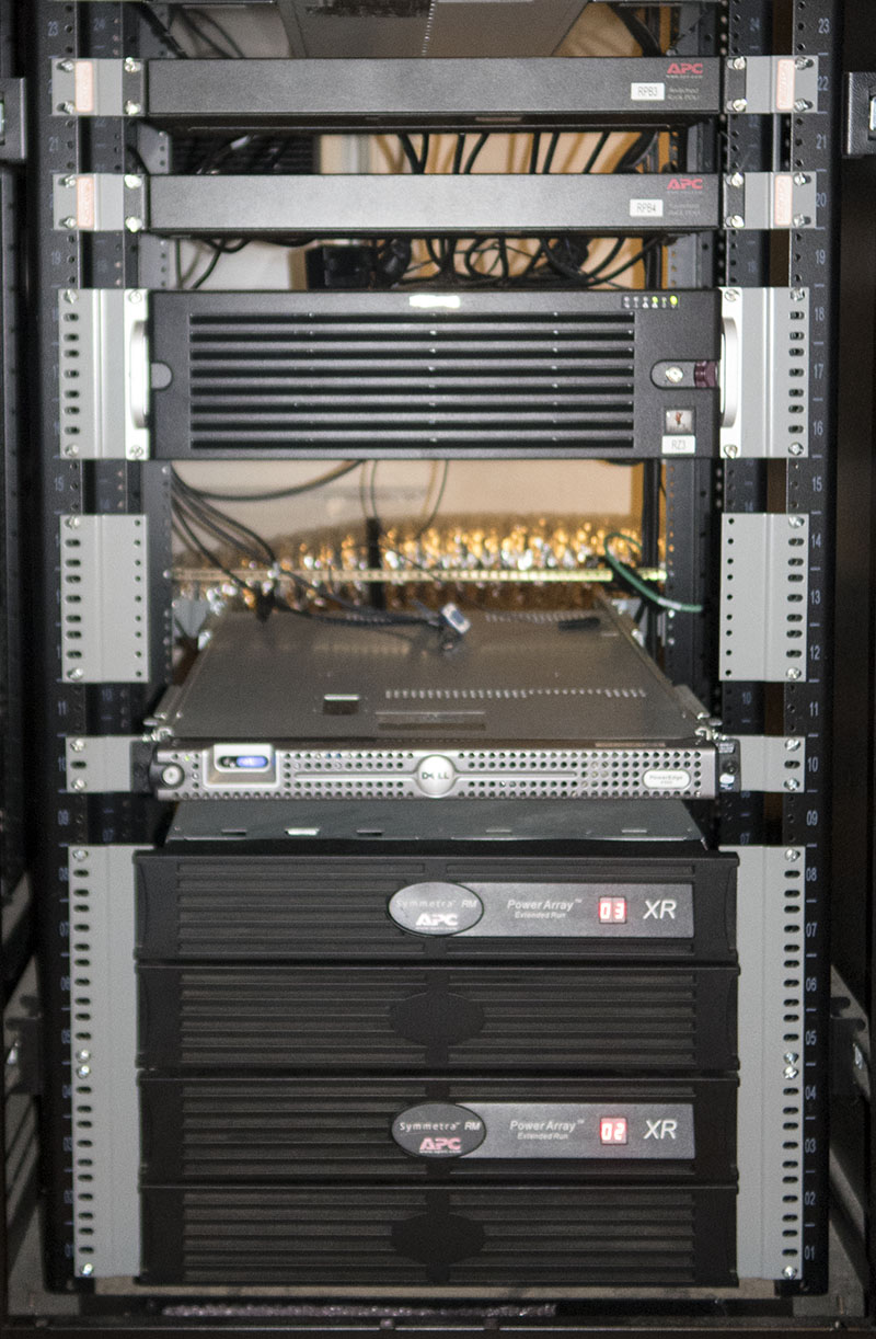
This is the bottom half of the right rack. From the top down are:
- Another pair of APC AP7900 PDUs. These handle the equipment in the
right-hand rack.
- A third RAIDzilla. This one is my test system, and it "only" has 32TB of
storage and 48GB of RAM.
- Empty space pre-wired for a fourth RAIDzilla. In the back you can see the
Ethernet, serial console, etc. cables. Further back, the corrugated silver hose
carries cold air to the racks for cooling during the warmer months.
- A Dell PowerEdge R300 server. This is the only system in these racks
that isn't for my personal use. It is one of four name servers my business
operates. It is here for geographic diversity (the other 3 are at various
facilities throughout the region).
- Two Symmetra RM XR (eXtended Runtime) battery frames. Each holds 4
additional batteries for the UPS in the left-hand rack. The UPS components
are spread out at the bottom of both racks to avoid making one rack
top-heavy and to avoid having most of the weight in one rack.
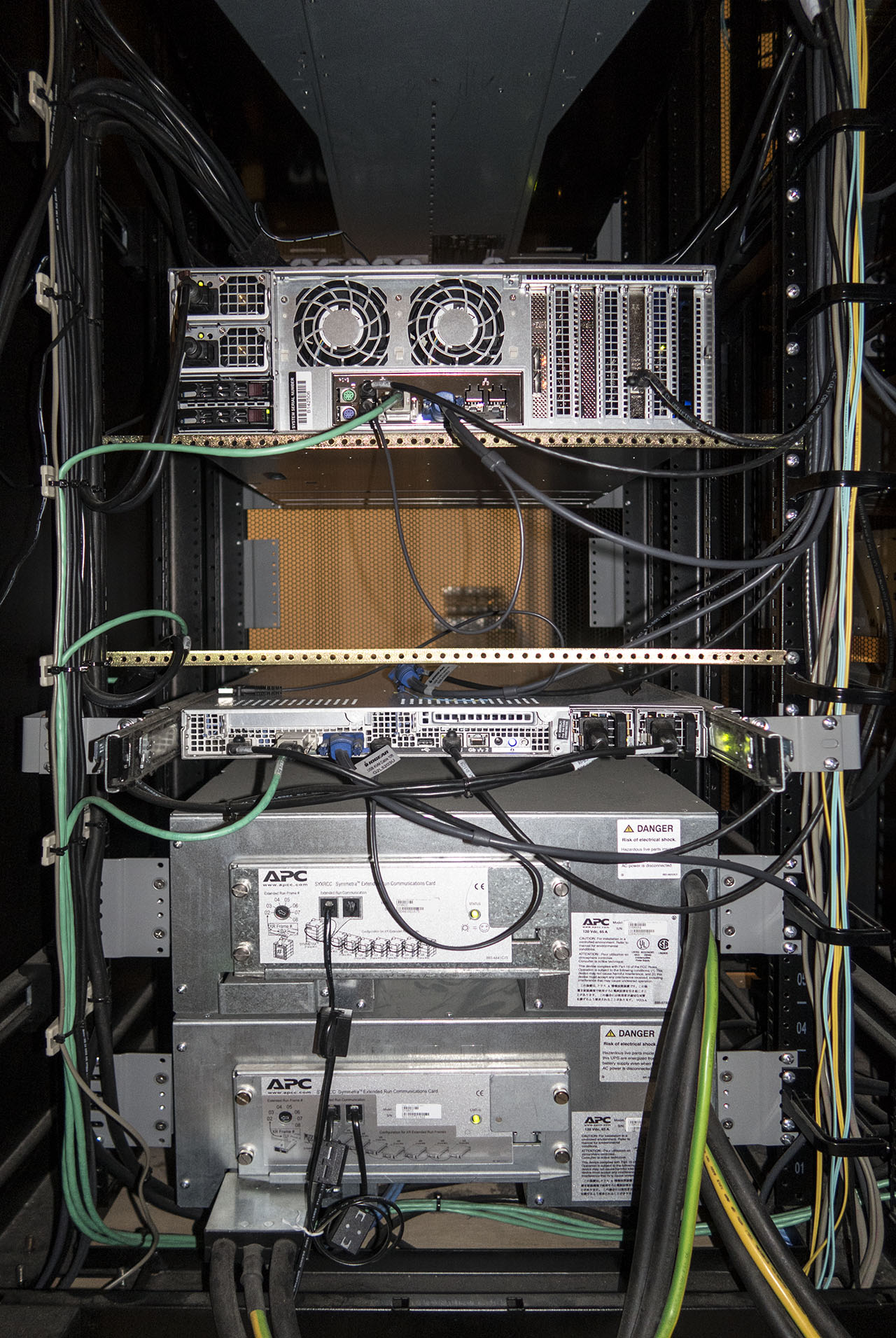
Moving around to the rear, this is the top of the left-hand (when
viewed from the front) rack. Anyone can (with a little effort) make the
front of a rack look good. The art is having the back look good as well!
- The green cables are the OOB (Out Of Band) serial cables from the Cisco
3845 router to the individual devices. Cisco uses ugly "octopus" break-out
cables, where each of the individual cables is always either too short or too
long. Instead, I am using a special rackmount break-out panel from Custom Cable
Industries. Just below that panel you can see a horizontal cable management
bracket, with the rear of the fiber patch shelf (beige) visible behind it. The
green cables are dressed on cable supports mounted to one of the rear rails.
Also on those cable supports are the various power cords.
- Below that is the rear of the Cisco 3845 router. As mentioned previously,
the yellow cable connects the Network Analysis Module to the Catalyst 3845
switch. The thicker grey cable above and to the left carries the 14 VoIP lines
to a patch block located in the other rack. The gold-colored bars below this
and other devices are supporting the backs of the devices, since they are both
too short to reach the back set of rails and do not have a provision for
mounting at the back.
- Next are the two Dell PowerConnect 8024 switches. The only connections on
the back are the redundant power supplies and the serial console ports.
- This is the back of the PowerDsine PoE injector. It only has a single power
cord.
- This is the back of the Cisco Catalyst 4948-10GE switch. Again, just power
cords. The large bundle of blue and black cables to the right are coming from
the Catalyst switch as well as other equipment. They go into vertical cable
management rings running along the right side of the chassis.
- These are the two Cisco ASR1001 routers. Again, just power cords (do you
see a pattern developing?).
- Here we see the back of the Dell PowerEdge R710. This system has all of its
connections on the back, so there's a bit more going on.
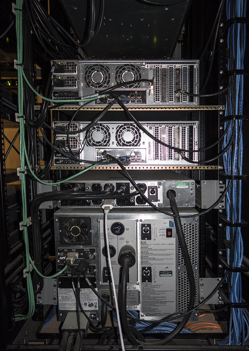
This is the bottom of the same rack. We have:
- A pair of RAIDzillas with their cabling. Lots more details are available in
the separate RAIDzilla 2.5 article.
- The APC SYTF2 120V step-down transformer. The four APC AP7900 PDUs are
plugged into this transformer. The white cable is for the QLOCKTWO clock shown
earlier. Its is powered from the UPS because it is a bit of a pain to set, and
the DCF77 radio time signal it would use to automatically set itself is only
available in Europe, not the US.
- The APC Symmetra RM UPS. The large silver connector and heavy black wires
on the bottom left connect it to the XR battery packs in the other rack.
Below the UPS you can see neatly coiled loops of wire and fiber. This is excess
length of various cables that leave the rack.
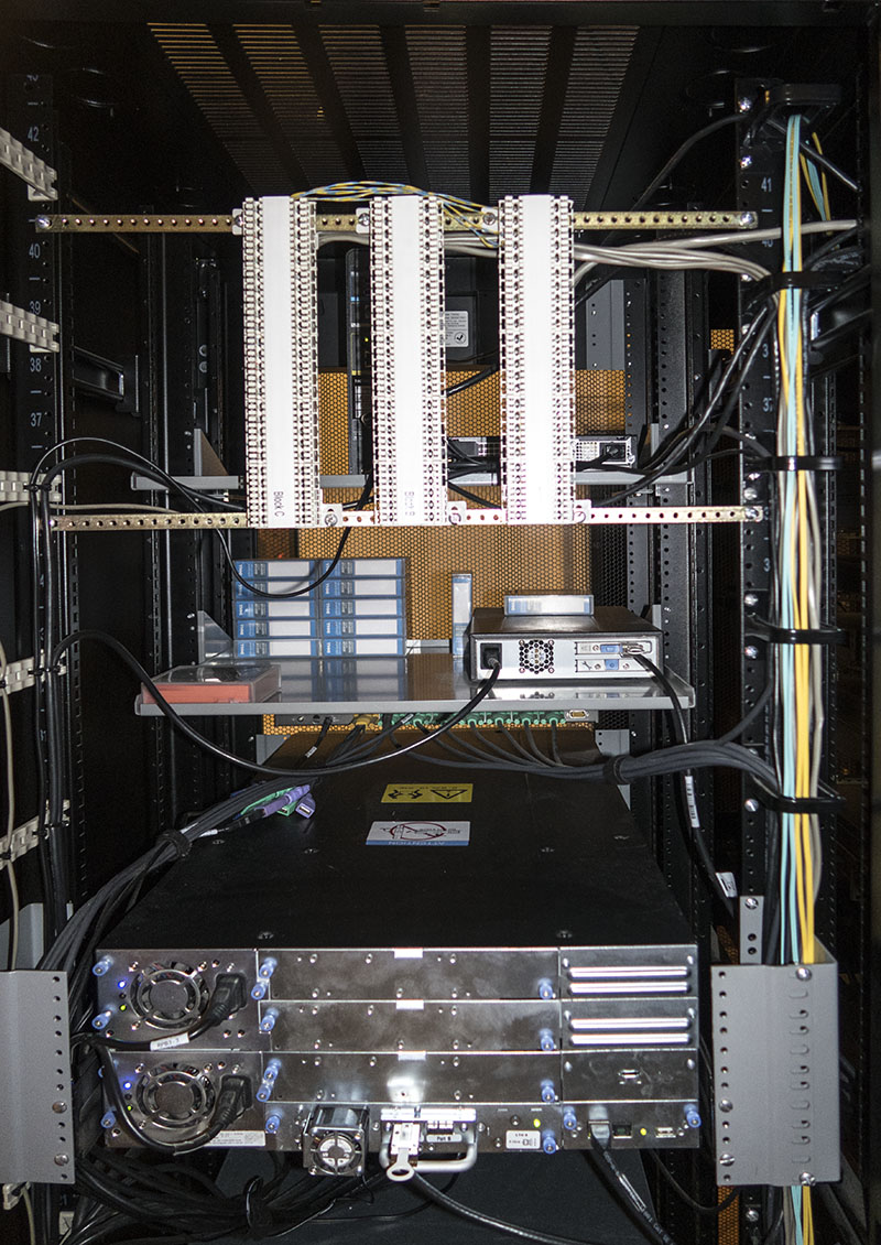
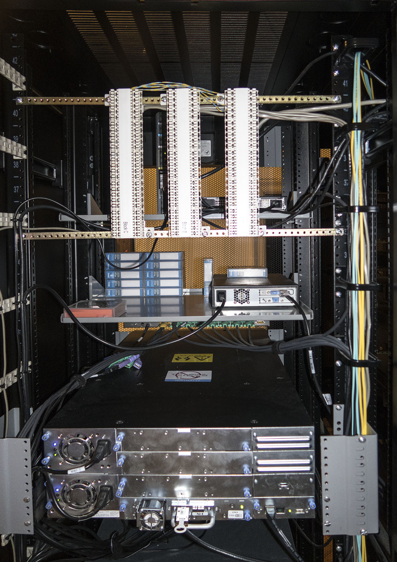
This is the top half of the right-hand (when viewed from the front)
rack.
- These are 3 Krone telephone patch blocks. The telephone cable from the
Cisco 3845 router connects here, as do various other cables to other parts of
the house. The blue and yellow striped wires you see above the blocks are
cross-connects between the various circuits. There is plenty of room for
expansion here! Toward the front of the rack, you can see the back of the
Dell Optiplex PC, the cable modem, and the PoE clock.
- This shelf holds the LTO4 tape drive and various data tapes, as well as a
cleaning cartridge.
- You can just barely see part of the IOGEAR GCS1716 KVM switch. The green
connectors are for various systems, and you can see those cables routed into
the vertical cable management rings on the right side of this rack. Also in
the rings are various fiber cables (more about these later on).
- This is the Dell PowerVault TL4000 robotic tape library. The LTO6 tape
drive is visible at the bottom, with 3 spaces for additional drives above
it. This library has the dubious distinction of being too deep for a 34" rack, so
5" extenders ("knuckles") are added to support the rear of the tape library's
mounting rails. We also see the "the manufacturer assumes every rack has
un-threaded round holes" mounting method for the rails. These screws go through
the 23" to 19" reducers without engaging the threads, and then thread into the
holes on the tape library's rails.

This is the bottom of the same rack. We have:
- The third RAIDzilla. See the description on an earlier picture for more
information.
- Mounting space for a future fourth RAIDzilla. You get a better view of the
pre-wired cables, compared to the earlier view from the front.
- Dell PowerEdge R300 server. This is also too deep for a 34" rack, but here
we can get away with 3" knuckles.
- Two APC Symmetra RM XR battery frames. The heavy black and green/yellow
cables are the actual battery voltage, while the much thinner black cables are
the communication cables.
This is a close-up picture of the top half of the network
equipment. I have already covered most of this above, but here is some
additional information...
The PowerConnect 8024F and 8024 switches are shown at the bottom of
this picture. They are both 24-port 10 Gigabit Ethernet switches. The 8024F has
24 SFP+ fiber ports, the last 4 of which also support copper (RJ45)
connectivity. The much rarer 8024 (no F) is the exact opposite - 24 copper
(RJ45) ports, the last 4 of which also support SFP+ fiber ports. The 8024
family did not have stacking hardware when released, although Dell subsequently
added the ability to configure any number of SFP+ ports as stack ports. These
switches are connected with 4 DAC (Direct Access Copper) cables to create a
40Gbit/sec stack link. These are the 4 black cables you can see at the right
side of both 8024 switches. The remaining 20 ports on the 8024F (upper) switch
have various SFP/SFP+ optics installed. Ports 1-4 have multimode Gigabit (SFP)
optics installed; ports 5-8 have single-mode Gigabit (SFP) optics installed;
ports 9-12 have multimode 10 Gigabit (SFP+) optics installed; ports 13-16 have
single-mode 10 Gigabit (SFP+) optics installed. These 16 ports allow me to test
most types of fiber equipment that I work on. Esoteric things like WDM (Wave
Division Multiplexing), BiDi (connection over a single fiber instead of a
normal pair of fibers), or extended-range optics (up to 100km and beyond) are
not installed in these switches. I'd probably use transponder boxes with
tunable optics if I anticipated doing a lot of this type of work. The sequence
of aqua / yellow / aqua / yellow fibers in ports 4, 8, 12, and 16 all route out
of the racks (you can see them in the cable management rings of the various
pictures of the rack backs posted above). They end up in neat coils
underneath the worktable, along with KVM cables, copper networking cables, etc.
The two aqua cables in ports 19 and 20 create a 20 Gbit/sec LACP trunk to the
Catalyst 4948-10GE below (not seen in this picture). The 5 copper cables at
the left side of the lower switch connect to the 4 RAIDzilla positions (one
currently empty) and the Dell R710 you're reading this on. The two blue cables
further to the right run to a jack on the outside of the rack, underneath
the table, and give me two 10 Gbit/sec test jacks.
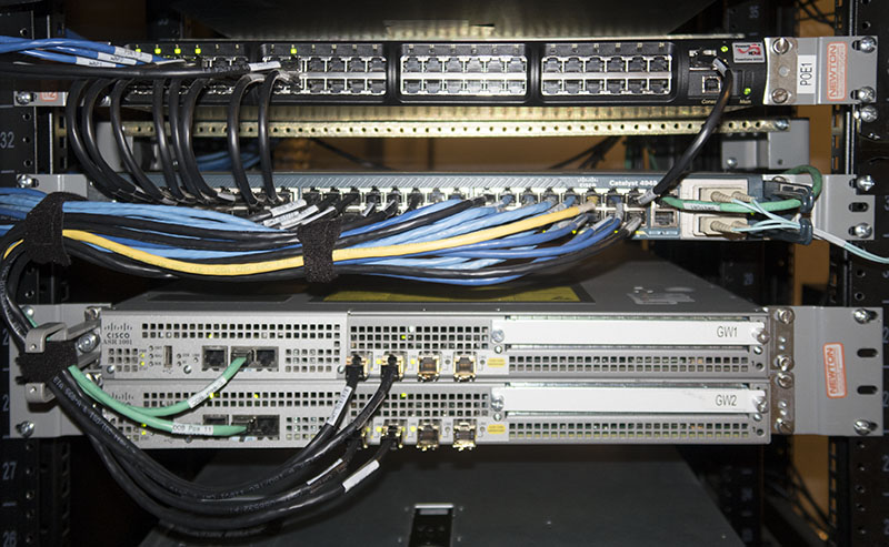
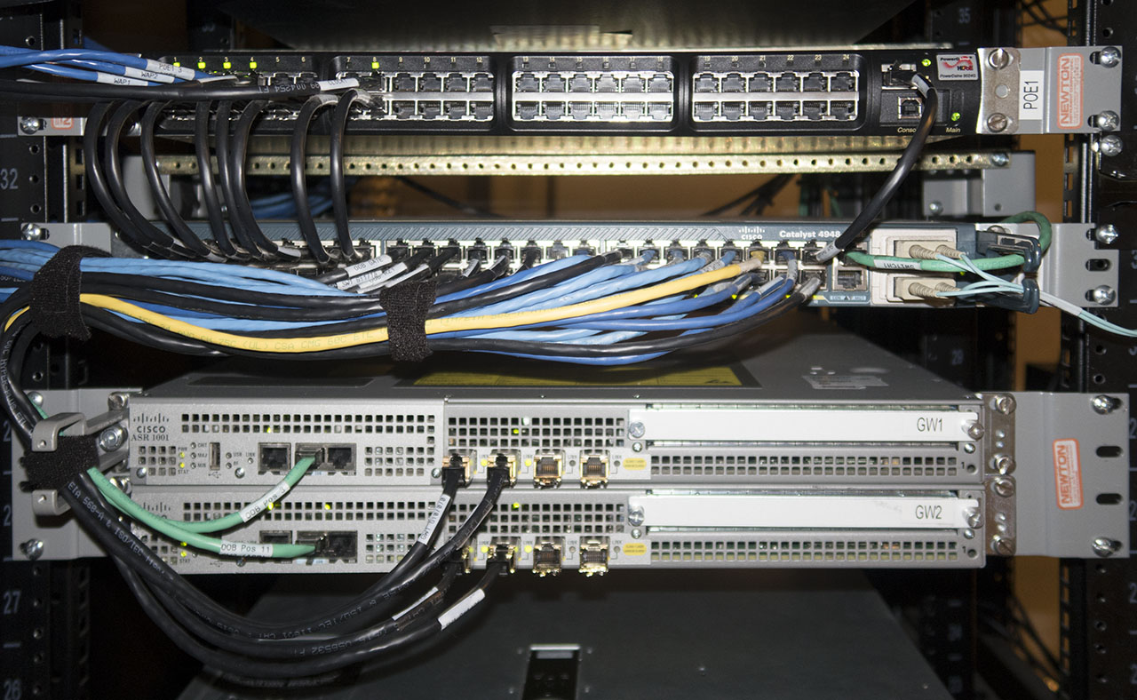
This is the matching close-up picture of the bottom half of the
network equipment. Again, I covered most of this above, but here is some
further information...
At the top of this picture is the PowerDsine PoE (Power over
Ethernet) injector. This is used to provide inline power to the various
wireless access points and the clock at the top of the right-hand rack. While
there are switches that have an internal PoE injector, I like the flexibility
of separate units - I can change the switch to whatever I want, without being
limited to specific PoE models.
Below the PoE injector is the Cisco Catalyst 4948-10GE switch. It
has 48 10/100/1000 ports as well as two 10 Gigabit Ethernet ports (using the
obsolete X2 transceiver form factor). This is a relatively full-featured
switch, running regular Cisco IOS. It can perform routing functions as well as
switching, although I don't use that feature. It has dual power supplies and a
hot-swap fan tray. The only issue is that this model tends to suffer the
"reboot of death" where the system light is red and nothing else happens. This
is due to overheating memory chips on the bottom of the board. I have
documented this issue in great detail here. This
switch has not had any problems in over 5 years, and I have a spare for it, so
I haven't felt the need to do anything different. The black cables plugged into
the switch ports are for various devices in the two racks and the blue cables
connect various devices outside of these racks. There are two Catalyst 4948
swiches (not the 10 Gigabit Ethernet version) elsewhere in the house which
connect the rest of my home equipment to this rack. Three of the blue cables go
to jacks underneath the table for various temporary / testing projects. The
yellow cable connects to the Network Analysis Module in the Cisco 3845 router.
All ports between the switches (including the 8024s above) are trunked and
carry a half dozen or so VLANs for various purposes.
Next is a pair of Cisco ASR1001 routers. They have four Gigabit
Ethernet ports each. The somewhat newer ASR1001-X has two 10 Gigabit Ethernet
ports and six Gigabit Ethernet ports, but is vastly more expensive - and then
you need to add licenses for the 10 Gigabit Ethernet ports and a 20Mbit/sec
throughput license in order to actually use them! These ASR1001s were obtained
very cheaply on eBay (average price $750) as they were from what the seller
described as "an unfortunate forklift accident" - apparently a large stack of
these was being moved and they either fell or hit a wall, as the chassis show
varying levels of damage. The power supply handles are somewhat bent (which you
can see if you look carefully at the picture of the back of the units, above),
but the most severe damage was to the SFP ports themselves - the connectors
were actually sheared off of the router motherboard!
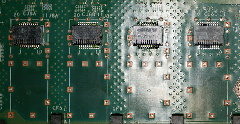
This picture shows the motherboard of one of the routers after
replacing two damaged connectors. The connector on the left (labeled "CJ8A" on
the picture) and the one next to the right (labeled "CJ8C") needed to be
replaced. The original CJ8A
connector was just cracked, while the CJ8C connector was completely sheared off
and rattling around inside the chassis. This picture was taken before I pressed
new SFP housings onto the motherboard (that's what the square copper-colored
areas are for - the housings are press-fit into those holes. This is something
that lets me save a lot of money, but unless you have the equipment to work on
boards like this, I wouldn't suggest that anyone else try this type of repair.