A DESCRIPTION OF THE OBSTACLES ENCOUNTERED, THE EXPERIENCE
GAINED, THE SUCCESS ACHIEVED, AND THE PLANS FINALLY
ADOPTED FOR RAPID AND ECONOMICAL
PROSECUTION OF THE WORK.
BY
S. D. V. BURR, A.M.
Illustrated by Working Drawings of all Details.
TWENTY-SEVEN PLATES
NEW YORK:
JOHN WILEY & SONS,
15 ASTOR PLACE.
1885.
PREFACE.
THE
general plans according to which some twenty-five hundred feet of the
Hudson River tunnel have been built are new : in executing them novel
methods have been introduced—great obstacles have been surmounted—most
valuable experience has been gained. By their aid a daily average of three,
four, and sometimes over five feet of tunnel was completed during shorter or
longer periods of time ; and when the heading was more than one thousand
feet from the shore an average of three and one-third feet of tunnel was
built each day for more than two hundred consecutive days—a performance
in engineering which far surpasses anything heretofore accomplished
through like material. So far some $1,100,000 have been expended.
Considering the great size of the tunnel, the character of the material passed
through, and the depth under water, this is one of the cheapest, if not the
cheapest, specimens of submarine tunneling ever accomplished, and this in
the face of the facts that many stages of the work were necessarily
experimental, that there were several serious delays—one caused by the
accident—and that there were constant hindrances to rapid and economical
progress.
In the following pages the aim has been to plainly, concisely, and yet fully
describe every stage of the work. Although the fundamental idea
embodying the use of compressed air was always adhered to, yet those
which might be termed auxiliary plans, or
3
4
PREFACE.
methods of doing certain pieces of work which presented features peculiarly
their own, were modified in accordance with the ever-changing
conditions. With the assistance of the drawings, which were so selected as to cover all the more important points, and which, taken as a
whole, constitute a very complete and easily understood history of the tunnel, it is hoped that the character of the difficulties may be
appreciated and the methods by which they were overcome fully comprehended.
The writer's opportunities for close and careful inspection have been most favorable from almost the beginning of the enterprise. It has been
his duty, while attached to technical journals of this city, to examine and describe the operations at the tunnel. Visits were frequent, and the
purpose was early formed of some day collecting and arranging the data obtained. The larger part of the articles then written appeared in
Engineering News, and were made up of notes almost invariably personally obtained in the heading of the tunnel.
The writer wishes to acknowledge the kind courtesy of Mr. D. C. Haskin,
manager of the company, who loaned the note-books and working-drawings of his
office.
S. D. V. B.
New York, January, 1885.
CONTENTS.
CHAPTER I.
Necessity for a tunnel—Hudson Tunnel Railroad Company—Location, length,
and grade of tunnel
CHAPTER II.
Method of building—Compressed air—Form and dimensions, and sinking,
of shaft—Air-lock in shaft—Effect of air-pressure upon silt—
Temporary entrance
CHAPTER III.
Starting tunnels—Method of building—Disposition of excavated
material—Bold plan adopted in beginning south tunnel—Difficulties
caused by old crib bulkhead—Removing temporary entrance—Accident
— Condition of work at time of accident
CHAPTER IV.
Plans for recovering the bodies and opening the work—Open cut, coffer-dam,
caisson—Description of coffer-dam and caisson—Air-locks in
caisson—Sinking caisson—Opening old air-lock—Forcing silt
into south tunnel
CHAPTER V.
Resuming work—Illumination—Condition of atmosphere—Air-compressors
—Steam supply—Telephone—Supplying material—Removing excavated
material
CHAPTER VI.
Shape, dimensions, and use of pilot—Advancing heading—Objects of iron
sheathing—Masonry—Leaks—Bulkheads in tunnels—Connecting
working-chamber with shaft—Perfected method of obtaining supplies and
removing silt—Suspension of work on New Jersey side.
5
6
CONTENTS.
CHAPTER VII.
Silt, analysis and physical properties—Its resistance to displacement
— Effect of compressed air upon silt—Dry, moist, and saturated
silt—The use of compressed air—Stopping leaks—Effect of
compressed air upon men and sensations in passing through the air-lock
CHAPTER VIII.
Plans for reaching grade of tunnels at New York side—Shaft or caisson
— Description of caisson—Air-locks—Its location—Method
of Sinking—Plans for starting tunnels—Cutting through side of
caisson—Iron bulkhead—Sizes of plates—Method of building
the tunnel—Bulkhead in tunnel—Handling material—Sand-pump
— Blow-out—Piles met—Work stopped—Boilers and air
compressors—Material required to complete tunnels
LIST OF ILLUSTRATIONS.
- Map showing location of tunnel.
- Profile and plan of tunnel.
- Cross-section through temporary entrance, looking toward shaft from
tunnel.
- (1) Longitudinal section through temporary entrance. (2) Plan,
shaft, temporary entrance, and tunnels.
- Perspective view showing condition of temporary entrance at time of
accident.
- Longitudinal section through shaft and tunnel showing method of
working.
- Coffer-dam showing caisson as suspended.
- Caisson—New Jersey side.
- Vertical air-lock in caisson : (1) Section and
elevation ; (2) front view ; (3) section through door and hinge ; (4)
inside view.
- Longitudinal section through shaft, caisson, and
tunnel after completion of working-chamber.
- Cross-sections through working-chamber and completed
tunnels.
- Side and end view of dirt-car.
- Plan and side view of dump-car.
- Longitudinal and cross section through pilot.
- Longitudinal and cross section through bulkhead in
tunnel—New Jersey side.
- Horizontal air-lock made in sections to facilitate
moving to front: (1) cross-section at end ; (2) side elevation-ends in
section.
- Longitudinal section and plan showing tunnels as
connected with the shaft.
- (1) Cross-section tunnel—New York side ; (2)
cross-section tunnel—New Jersey side.
- Views of caisson—New York side : (1)
Longitudinal sectional elevation ; (2) transverse section ; (3) half
plan.
7
8
LIST OF ILLUSTRATIONS.
- Sectional elevation through caisson
and tunnel—New York side.
- Cross-section and plan showing piles met—New
York side.
- Showing method of building tunnel through sand—
New York side: (1) cross and longitudinal sections—plates in upper
portion of section ; (2) Plates in half of section ; (3) Section sheathed and
ready for masonry.
- End elevation of iron bulkhead.
- Showing projection of rings of plates—working in
sand.
- Sizes of iron plates—New York side.
- Longitudinal section, plan, and cross-section through
bulkhead—New York side.
- Longitudinal section through tunnel—New York
side.
TUNNELING
UNDER THE
HUDSON RIVER.
CHAPTER I.
NECESSITY FOR A TUNNEL—HUDSON TUNNEL RAILROAD COMPANY
LOCATION, LENGTH, AND GRADE OF TUNNEL.
THE
Hudson River, flowing between New York City and Jersey City, where seven great
railroads carrying the bulk of freight from the West have their termini, has
always most effectually delayed transportation, and rendered impossible the
sure, and at the same time the quick, delivery of freight. The magnitude of
the barrier thus presented may be conceived when we remember that New York
City is not only the largest shipping port in the country, but is also the
distributing point for freight between the South and West and the East, and
from the East to centres West and South. We therefore find that the few hours
lost in crossing the Hudson affect not only this immediate vicinity, but they
also affect in a much more marked degree every point having business relations
with New York, or through New York to points beyond.
The passenger side of this question is, perhaps, the more important, although
the reduction by the use of a tunnel would amount to an average of but a few
minutes ; but these short periods consumed by ferriage become worthy of most
careful consideration in this age of quick travel and obstinate competition.
There are but two plans of obviating this difficulty—building a
9
10
TUNNELING UNDER THE HUDSON RIVER.
bridge or a tunnel. The tremendous cost of the first, arising from many
causes which will appear to the observer, places it out of the question.
Projects for tunneling under this stream, which has a swift tidal current and a
deep channel, have long been discussed, but by all of the old and established
methods of submarine tunneling the cost has stood in the way, for the simple
reason that, if built with private capital, the charges or toll would have to be
so large, in order to pay an interest on the amount invested, as to make its
use practically impossible. The benefit to be derived was not commensurate
with the expenditure when it could only be obtained at the rate of a few
inches per day ; consequently it became evident that some cheaper plan must
be brought forward before a roadway could be built under the river. That
some of the established plans were perfectly feasible is most probable, and
that they could only be prosecuted slowly and at excessive cost is most
certain. The great size of the tunnel was no mean obstacle, for, in order to
accommodate travel, it would have to be, if single, large enough for two
tracks, since a single-track tunnel would not clear away the obstructions to
transportation, and would cost much more than one-half the sum which one
carrying a double track would. The question then resolved itself into one
double-track single tunnel or two single-track parallel tunnels.
For the purpose of constructing a railroad through a tunnel under the Hudson
between the two cities the Hudson Tunnel Railroad Company was organized,
with a capital of $10,000,000, under the general railroad laws of New York
and New Jersey. This corporation is independent of the railroads now
existing, and was dependent solely upon its own financial ability to carry out
the work it proposed.
In locating the Hudson River Tunnel three questions came prominently up for
consideration. The various routes, upon any one of which the tunnel could
have been begun, while differing essentially from each other in some points
of minor importance, yet presented the same general features regarding the
material to be passed through and the engineering difficulties to be
surmounted. The river at this locality varies but little in width or depth, being
a trifle over a mile across and sixty feet deep in the channel, and the shores
and bottom do not change much either in composition or
11
TUNNELING UNDER THE HUDSON RIVER.
contour between the extreme points at which the tunnel might have been
located. The bed of the river consists of silt, which extends from the New
Jersey or western side nearly or quite across the river ; upon the New York
side, near the shore, some rock is encountered, between which and the shore
sand underlies the silt.
Owing to this peculiarity of formation the tunnel would be embedded for
nearly its whole length in silt, no matter where its location might be ; and,
governed by these circumstances, the estimated cost of the work in each of
the locations did not change much when confined to the tunnel proper. The
approaches, of course, varied considerably with each location, and the
selection depended directly upon the value of the land to be acquired at each
terminus, thereby influencing the total cost of the work as a whole.
But the final and paramount question, upon which the real success of the
scheme depended, was what might be termed the accessibility of each end,
or, in other words, the convenience of using the stations and their adaptability
to the requirements of trade. Upon the New York side this was governed
primarily by the fact that it should be so situated as to be easily reached from
the centre of the city, and yet the site should not be in a neighborhood in
which the land damages would be so great as to be in reality prohibitory.
Upon the other side of the river it had to be so located that the great
railroads having their termini there could acquire access to it at a minimum
cost.
After a careful examination of all the questions involved, the tunnel was
finally located on a line extending easterly from Jersey Avenue (Jersey City),
on Fifteenth Street, to Hudson Street, about 3,400 feet ; from this point it
curves five degrees northward to the New York City bulkhead line at the
foot of Morton Street, about 5,500 feet, and thence again slightly southward
about 4,000 feet to the eastern station. As will be seen by consulting the
accompanying map, this line places the eastern end in
one of the best
locations in the city, and also furnishes the most convenient point upon which
to concentrate the various railroad lines upon the New Jersey side with the
least possible injury to existing interests. More than this, the line encounters
as little, if not less, rock—which never comes nearer than 28 feet from the
bottom of the river, and is wholly confined to a small knoll near the eastern
shore—than any other,
12
TUNNELING UNDER THE HUDSON RIVER.
and insures plenty of head-room in silt. The composition of the material
encountered along the entire line is shown very clearly in the plan and profile
(Plate II.)
This plate also shows the grade of the tunnel. The slope from the western
end is two feet in a hundred to a point about 1,600 feet from the shore,
where the slope changes to one foot in one hundred ; this continues to within
1,300 feet of the eastern shore, where, for a distance of 300 feet, it is one
foot in one hundred. For 500 feet the grade is four in one hundred, and for
2,000 feet the grade is three feet in one hundred, thence to station the grade
is moderate, conforming with the surface. The grade accords very nearly
with the slope of the river-bed, and became necessary from the fact that it
was decided that at no point should the crown of the arch approach nearer
to the water than 15 feet. This was to insure safety in the work and to guard
against any change which might take place in the future in the bed of the
river.
CHAPTER II.
METHOD OF BUILDING—COMPRESSED AIR—FORM AND DIMENSIONS,
AND SINKING, OF SHAFT—AIR-LOCK IN SHAFT—EFFECT OF AIR-
PRESSURE UPON SILT—TEMPORARY ENTRANCE.
THE
plan or method of carrying the work forward was by the use of
compressed air, as applied in patents granted to Mr. D. C. Haskin, the
president and manager of the company. This plan, briefly stated—for we shall
describe its exact operation in detail further on—consisted in
maintaining an air-pressure in the work about equal to the hydrostatic head.
It was well known that if these two elements—the air-pressure inside
and the water-pressure
outside—could be so controlled as to maintain a constant and unchanging
equilibrium, the material separating them need not be either of great size or
strength. It was calculated that the silt, when in proper condition, would have
tenacity or consistency enough to answer this object ; and although it was
known that this would only serve the purpose for a brief time—the exact
duration could in no way be experimentally determined—it was thought that
there would be ample time to place and secure the iron plates forming the
exterior of the tunnel. It was known that, with the plates once in position and
bolted together, the interior air-pressure would take the place of struts to
keep them in position—a feature which would not only relieve the working
space of encumbrance, but would give a much better support for the plates
while the masonry was being put in. A plate 30 by 50 inches would be
subjected, at a depth of 45 feet, to a pressure of 30,000 pounds. At a normal
interior pressure this plate would have to be supported at several points in
order to prevent bending, or, in case a single strut were employed, it would
have to be made of great thickness and the strut would be of a size so large
as to most seriously occupy the space. But with the use of compressed air at
20 pounds pressure per inch the plate would be supported at every point and
its thickness would become a question of minor importance. It is hardly
necessary to state that these
13
14
TUNNELING UNDER THE HUDSON RIVER.
things were all carefully considered before the work was begun. How well
compressed air alone answered the purpose will be found as
we advance with the undertaking.
After a year spent in taking soundings and boring on the line adopted, work on
the tunnel was begun in November, 1874, it having been decided to sink a shaft
on the New Jersey side near the river line, and from the side of the shaft
start the tunnel. The position of the shaft in relation to the tunnels is
clearly indicated in the plan-view in Plate IV.,
and its position on the shore, 83 feet from the bulkhead-wall, is shown in
Plate VI. It is circular in
form, having an inside diameter of 30 feet, an outside diameter of 38 feet,
the thickness of the wall at the bottom being 4 feet and at the top 2 1/3
feet ; the batter of the outer surface is one inch in three feet, or a total
of 20 inches. It was sunk to a depth of 60 feet below the ground-surface,
passing first through 9 feet of loose ash-filling, then 50 feet of silt, the
bottom finally resting in sand. A shoe was first built in an excavation a few
feet deep, and upon this the masonry (brick) was laid, the mass sinking as
material was removed from under the shoe.
The shoe was made of 10 by 12-inch yellow pine, held together in ship-work
style by drift-bolts. It had a cutting edge of boiler-iron, and was 4 feet
high by 4 feet wide at the top, the section being triangular. Upon each of
the east and west sides of the shaft there was built a false piece 24 feet
high by 26 feet wide, having an elliptical form, and which was to be finally
removed to make room for the approach and the tunnel. These sections were
laid in common mortar—the rest of the shaft being laid in Rosendale
cement—and during the sinking caused considerable trouble, as the false
work in the river-side was forced in, by the pressure of the earth, to such
an extent as to require interior bracing. The projection at the top amounted
to 7 inches, decreasing to nothing at the bottom. The bracing consisted of
heavy yellow-pine timbers formed into a hexagonal collar-brace ; four sets,
at varying heights, were put in, and, while they served the purpose admirably,
they also acted as supports for the platforms afterward required.
Sinking of the shaft continued until December 15, 1874, when, after thirty
days' work, the shoe was 14 feet below mean high water, when work was stopped
by an injunction obtained by the Delaware,
15
TUNNELING UNDER THE HUDSON RIVER.
Lackawanna & Western Railroad Company. On account of litigation work
was not resumed until September, 1879.
Material was taken out by a hoisting-engine, the vibrations of which caused
that part of the shaft nearest to it to sink faster than the remaining
portions ; and to overcome this difficulty the engine was moved about, when
the settlement could be better controlled. On November 3 the shaft was in
position, with the shoe 54 feet below mean high water, or 60 feet from the
surface ; the average rate of progress was one foot per day. During the
sinking no difficulty was experienced in keeping the shaft free of water by
the aid of an ordinary hand-pump ; but as soon as the shoe entered the sand
stratum water poured in at the rate of about 200 gallons per minute. While
making the excavation two pumps were used alternately to keep the water
down—an Andrews pump of 300 gallons' capacity per minute, and a
Pulsometer of 100 gallons' capacity.
This movement displaced all the earth immediately adjacent to the shaft. The
silt moved down the outside and under the shoe, and was followed by the
ash-filling, the approximate positions, as determined later on, being indicated in
Plates V. and VI. The appearance of the ashes, low down on the side of the
shaft, was the direct cause of much trouble later on when the work was
being prosecuted in this locality, since the ash mixing with the silt injured the
latter's tenacity and made its behavior under air-pressure uncertain. The
displacement was also aided by the sinking of the shaft itself, since, as it
descended, the friction of its outer surface tended to dislodge the material
and subsequently made the passage of the water down the side much easier.
Building projecting courses about the shaft would not, in all probability, have
obviated the difficulty ; and if the work had been arrested for a time just
before the shoe entered the sand stratum the water would not have been
finally excluded from the bottom. If the latter course had been pursued it is
doubtful if the shaft could have been started again on its course, so great is
the clinging power of the silt when it has been allowed a little time to settle
around an object. Piles driven along this shore move down easily when
quickly driven, and when driven too far may be pulled up, no settlement taking
place after the silt has had time, to accommodate itself to the new conditions.
In order to lay the concrete bottom the water was confined as
16
TUNNELING UNDER THE HUDSON RIVER.
much as possible in covered chambers, a number of 4-inch iron pipes
being laid (radiating) from a well having an open-slat wooden curb 4½ feet
across at the bottom, 2 feet at the top, and 4 feet in height ; this was lined
with loose brick and placed at its full depth in a convenient situation in the
bottom. That portion of the bottom least exposed to water was first covered
with a foundation of securely-embedded dry stone from 12 to 18 inches
deep, and then concrete was put on in layers from 8 to 12 inches deep. An
adjoining section was then treated in the same way until the entire bottom
had been put in and the water confined to the well-hole. The average
thickness of the concrete was 2¾ feet—that at the centre being 2½ feet
and the sides varying from 3 to 3¾ feet. The concrete was mixed as
follows : One cement, two sand, two stone, and one gravel. Water, carrying
sand with it, still came through the well, the filling of which with dry stone
only stopped the sand to a small extent. Consequently, a 12-inch stand-pipe
was carried up from the well for a distance of 25 feet, at which point a
reducer was put on and a 4-inch length extended to above high-water level.
The water in this pipe rose and fell with the tide, but not in the same
proportion, nor did the level reach that of the river. The well-hole about the
pipe was at last filled with concrete, which was mixed in bags and placed in
the hole, which had been previously cleaned out and the sides dug away so
as to form a cone. Other attempts to concrete this portion had been
unsuccessful, as the water-pressure was sufficient to wash out the concrete
as fast as it was put in ; but by using bags the concrete was held until it had
time to set, the outwardly and downwardly sloping sides preventing any
dislodgment.
The air-lock (Plate IV.) was a cylindrical tube of
3/8-inch boiler-iron, built up
of plates 3 feet wide and extending half-way round. Although it was 15 feet
long by 6 feet in diameter, it proved to be admirably adapted for convenient
use. In each end there was a door 3 feet wide by 4 feet high, and so hung
upon strap-hinges 3 inches wide by ¾ inch thick, placed 10 inches above
the bottom and the same below the top, and extending across the door, that it
swung inward or toward the air-pressure. The door-frame was of 4-inch
angle-iron, riveted to the head, which was stayed by five 2-inch braces that
were 2 feet long and were riveted to the shell. The door was further
strengthened by two strips of 4-inch T-iron placed
17
TUNNELING UNDER THE HUDSON RIVER.
horizontally. The doors and heads were each an inch thick. There was a
bull's-eye in each door and one in each head beside the door, made of 1-inch
thick glass 9 inches in diameter, the exposed portion being 7½ inches
across. Extending entirely through the air-lock were thirteen pipes varying
from 1 to 4 inches in diameter and used for air and water supply, electric-light and
telephone wires, blow-out pipes, etc. There was also a 6-inch pipe leading through
the inner end of the air-lock and passing through the side of the lock to the bottom
of the shaft. There was also a collar of angle-iron 6 inches wide and ½ an inch
thick, securely fastened around the outside, against which to brace to secure the
lock in position. The air-lock was used for the passage of men and materials, and
was supposed to be the largest one ever built.
In the side of the shaft, at the top of the false piece previously mentioned, 29 feet
below top of shaft, an opening was made to receive the air-lock. (In order to show
the nature of this silt it may be well to state here that it gradually and regularly
pushed its way through a small opening which had been made in the shaft, keeping
the form of the hole until it projected a little way from the wall, when its own weight
broke it off and it fell to the bottom but still retained its shape.) This opening was
not carried completely through the masonry, a thin shell of brick being left upon the
inner side. The air-lock was then lowered down the shaft until it was opposite the
opening, when, by means of hydraulic jacks braced against the opposite wall, it was
forced through until it projected 4 inches beyond the outside of the shaft. Then the
brick wall was fitted around the air-lock, being strengthened by a collar of yellowpine timber, and securely braced from the opposite side of the shaft so as to prevent
any change of position upon the air-pressure being put on from the front.
To remove the temporary door of boards which had been secured to the forward
end of the lock, and which was held by the pressure of the earth against it,
and begin the tunnel work was the next operation in order—one which was watched with
absorbing interest, since the time had come to practically test the adaptability of silt
for the work, as illustrated by its air-resisting properties. Men entered the lock,
closed the rear door behind them, and after an air-pressure of 12 pounds to the
square inch had been put on they re-
18
TUNNELING UNDER THE HUDSON RIVER.
moved the temporary door, when the silt was cleared slowly away until the iron
door could be put in place and swung wide open. It was soon found that silt,
when of the proper degree of moisture, was impervious to air, and the great
problem, that the silt would hold the air and the air would hold the
silt, was practically solved. At this time it was the intention to build a
double-track single tunnel, 24 feet high by 26 feet wide in the clear, and the
excavation was extended partly around the shaft, and on January 2, 1880, the
chamber dug was 6 feet high, 15 feet wide, and 4 feet deep. No attempt was
made to protect the silt from the air, which gradually forced back the water,
minute holes first indicating an excessive dryness ; these holes increased in
size and developed into cracks, which extended up through the silt, in
about four days, to the loose ash-filling that had been carried down by the
shaft, as already mentioned, and through which the water flowed as they
increased in size. Before the water found a passage the roof began to fall ;
first small, then large pieces of dry silt would become detached and drop. The
top was kept in place four days by the air-pressure, but as the water had a
disintegrating effect upon the silt, which seemed to mix with, and be held in
suspension by, it, the excavation was refilled soon after the cracks appeared,
the men retiring into the air-lock and closing the door.
A hole was now dug at the surface immediately above the inner end of the lock,
30 feet wide, 9 feet below high water, and extending 20 feet from the side of
the shaft toward the river. Carefully spread over the bottom of this hole, and
carried a short way up on the shaft, was a canvas, held down by heavy timbers,
upon which the excavated material was replaced. This expedient was adopted in
order to prevent the entrance of water into the work next to the shaft. While
this work was being performed the plates for a temporary entrance leading to
the inner lock-door had been made. This entrance (Plate
IV.) was a tube 8 feet
long by 6 1/3 feet in diameter, composed of plates 2½ by 4 feet, with
3-inch angle-irons riveted along each edge. This tube lapped over the
projecting part of the air-lock, to which it was secured, and was made of iron
½ an inch thick ; this amount of strength being considered requisite, since
the tube was designed to prevent the air-lock door from ever becoming wedged
should a caving of the roof take place.
19
TUNNELING UNDER THE HUDSON RIVER.
From the end of the temporary entrance there was built a series of iron rings
— to get away from the shaft into undisturbed silt—
(Plates III., IV.,
and V.), each being 2 feet wide, 3/8 of an inch thick, and each being 18
inches larger than the one just preceding it. These rings were secured
together at the top, which sloped so as to meet the proposed grade of the
tunnel. The angular spaces formed by the lower portions of the rings were
filled temporarily with concrete. The diameter of the largest ring was 20
feet. To place the plates forming these rings in position an excavation was
made in the top adjoining the plate already in, when the centre upper plate
of the next ring was put up and bolted to the finished work. Then an
excavation was made at each end of this plate, to which the second and third
plates were joined. As the circles were eccentric to each other, touching only
at the top, the centre plates could only be held together by two or three
bolts. The air-pressure was increased as the work advanced, and thus early it
was learned that there could be no rule laid down by which to estimate the
exact pressure needed. The correct amount fluctuated considerably, and to a
certain degree was independent of the hydrostatic head ; the density and
composition of the material directly overhead exerted a direct influence upon
the pressure, which could only be determined by closely watching the behavior
of the earth under the pressure it was at the time exposed to, and change the
air accordingly. After the completion of the eleven rings constituting the
entrance the north tunnel was started, it having been decided to build two
parallel single-track tunnels instead of one large one.
CHAPTER III.
STARTING TUNNELS—METHOD OF BUILDING—DISPOSITION OF EXCA-
VATED MATERIAL—BOLD PLAN ADOPTED IN BEGINNING SOUTH
TUNNEL—DIFFICULTIES CAUSED BY OLD CRIB BULKHEAD—RE-
MOVING TEMPORARY ENTRANCE—ACCIDENT—CONDITION OF WORK
AT TIME OF ACCIDENT.
THE
starting of this work was very difficult, requiring much care and watchfulness
at every step. The north tunnel was the first one began. The entrance, or
connecting-chamber, as it was afterward more commonly called, being but 20
feet in diameter at its river end, would only cover the adjoining walls and
not one-half of the arch and invert of each tunnel. To build the outer
sections was, therefore, the hazardous part of the undertaking. But
experience had already shown that, having a firm foundation to which to
attach an iron plate, the work could be readily carried on in any
direction or form. A space was excavated large enough to permit the insertion
of a plate, which was secured by bolts to the plates of the last ring which
served as a foundation to work from. Thus the work was prosecuted plate by
plate until an iron band, or shell, of a size equal to the exterior of the
tunnel, was constructed, in which the brick-work was laid. The vertical space
between the north side of the entrance and the outer side of the north tunnel
was securely bulkheaded, the plan being to build a certain length of each
tunnel, and then return to replace the temporary work by uniting the tunnels
and shaft. The air-pressure, about 18 pounds to the square inch, held the silt
firmly in place while the rings were being made.
From this time the tunnel was built in the following way, which is very
plainly shown in the drawing (Plate VI.) Silt was
removed until the top centre plate could be put in and bolted to the one
behind. Then a plate was put in at each side and bolted to the centre plate
and to the ring. When this circle had been carried down the sides for some
distance another was commenced and built in the
20
21
TUNNELING UNDER THE HUDSON RIVER.
same manner. When four rings of plates had been put up and thoroughly
braced as additional protection in case of a reduction in the air-pressure,
this iron-lined chamber was cleaned out and the masonry laid, thus completing a
section of 10 feet. Both the ironwork and masonry were advanced in sections
varying from 10 to 15 feet in length. During the first few weeks the rate of
progress only averaged about 1 foot per day, but as the men became more
familiar with the work which was soon put in systematic shape, the rate
increased to an average of nearly 5 feet of completed tunnel every 24
hours. The heading, which was cut into steps, as indicated in the drawing, was
entirely exposed to the air-pressure, no attempt whatever being made to
sheathe any part of it ; but all digging to advance the heading was done
carefully and without undue haste, since at any moment a less compact
material, or "pocket," might be opened. It was the duty of some of the men to
watch for leaks in the temporary work at the entrance—which, if of some
size, could be detected by the noise made by the out-rushing air ; when small a
candle passed close to the surface would show the leak by the flame being
drawn in the hole by the escaping air. The leaks were easily controlled by the
application of fresh silt.
About one-half of the excavated material—which was conveyed to the air-lock
upon a car, the track being extended as the work advanced—was removed
from the tunnel, the remainder being left in the finished work. The machinery
and all the operations connected with the removal of earth and the introduction
of supplies will be described in detail further on. At this time the silt was
removed by being first mixed in a trough—shown to the right in
Plate VI.—with water, and then blown through a
6-inch pipe by the air-pressure to the shaft from which it was hoisted to the
surface and conveyed to the low land just back of the works.
The shell was made of ¼-inch boiler-iron cut into plates 2½ feet
wide and 3 and 6 feet long. On each of the four sides was a flange 3 inches
wide ; these flanges were pierced with holes at every 6 inches, through which
each plate was bolted to the four plates around it. To give additional
strength to the cylinder the joints were broken. The masonry was 2 feet thick,
of hard-burned brick laid in cement. Four classes of men were employed upon
the work, which was pushed forward night and day—miners, welders,
laborers,
22
TUNNELING UNDER THE HUDSON RIVER.
and masons. The miners advanced the heading, the welders put up and
united the plates, the laborers handled the diggings, and the masons placed
the brick-work. The men worked in shifts of 8 hours each each shift consisting
of 28 men, who were allowed half an hour's recess in which to come to the
surface to eat their meal ; but it was so arranged that one-half, or 14 men,
remained on duty while the others went out.
The lines and grades of this portion of the north tunnel, which on July 1,
1880, had been finished for a distance of 281 feet from the shaft, were not
good, and the shape was irregular. The reasons ascribed for this were that
the plates, which were bent to a circular form, were joined to make elliptical
rings, that the iron was too light, and that the plates were extended too far
beyond the brickwork. At one time the plates on top were over 50 feet
ahead of the masonry, the result being an almost imperceptible settlement,
resulting in distortion. This was remedied by increasing the air-pressure and
by not carrying the plates too far in advance of the finished work.
In order to prevent the escape of air through the pores of the brick, ordinary
red-lead paint was tried with but little success ; much better results were
obtained by a wash of pure cement put on in several layers.
The plan pursued in beginning the south tunnel was a bold one that proved to
be rapid and successful in execution. The plates were inserted in small
openings, as in the case of the north tunnel, but instead of removing all the
material from the iron cylinder a centre core of silt was left. This core was
about 5 feet long and a little less in size than the inside of the completed
masonry. The men burrowed down each side and under this core, forming an
annular chamber about 3 feet wide. As the excavation was carried down the
plates were put in, and were supported by struts resting against the core, a
cross-section of this part resembling a large wheel having an immense hub
of earth, short, thick spokes, and a thin iron tire 5 feet in width. In
justice to Mr. Anderson, the superintendent, it may be stated that he asked
no one to venture under this core and put in the masonry ; but, recognizing
the fact that there was a possibility of the mass suddenly settling, he went
under it himself and laid the first bricks in the invert. After this the
masonry ring
23
TUNNELING UNDER THE HUDSON RIVER.
was quickly completed, yet it was some time before the core, which moved
slowly and regularly, had settled down. The tunnel was then pushed forward
until the advance plates struck the old wooden-crib bulkhead, when work on
both tunnels was stopped, and operations were directed toward removing the
temporary entrance, or connecting-chamber, as this was too weak to stand the
increased pressure required at the heading, and permanently uniting the shaft
and tunnels. At the end of the north tunnel a bulkhead was built of 4 by 6-inch
timbers laid horizontally and closely together against the silt, with their ends
resting against the ends of the brick-work ; behind these were vertical timbers
of the same size, still back of which was another row of horizontal timbers, the
last two rows being 3 or 4 feet apart. The whole was braced by struts
supported in openings left in the masonry.
Tunneling through the wood and stone crib, which in some places projected
half through the tunnel, was a difficult task. The ends of the piles had to
be cut off and the horizontal timbers removed so as to clear the iron plates.
It was through this old bulkhead that the water came at the time of the
accident ; it caused a great deal of trouble when recovering the bodies of
the men and beginning anew.
The first work associated with the removal of the connecting-chamber was
directed toward the last or largest ring. The two plates adjoining the centre
one were taken down and the silt dug out, so that when the plates were
reinserted they were on the curve to be formed for the new work, the object
being to construct a bridle, as it were, to cover both tunnels with one span or
arch so as to leave a large chamber, as shown in Plate
XI. In this way four rings were removed and the masonry built upon, as
shown in Plate V. The plates in the roof of the
remaining rings were then taken down, their place being supplied by the hood
forming the crown of the new work. This hood reached from the completed work
to the shaft, which it joined 3 feet above the air-lock, and then extended
down each side and against the shaft as close as it could be well fitted, as
shown in the cross-section (Plates III.,
IV., and V.) This roof was
about 30 feet in width and was braced by timbers, as indicated in the
drawings. The general condition of the work and the arrangement of the
machinery at this time are shown in Plate
24
TUNNELING UNDER THE HUDSON RIVER.
VI.—the north tunnel (not shown) had been
completed for nearly 300 feet under the river.
At about 4.30 o'clock on the morning of July 21, 1880, when one-half of the
men had returned to their work and the other half had started for the air-lock
to pass out for their period of rest, a leak occurred, the air escaping up along
the side of the shaft. The leak was probably caused by a plate not being
properly secured against the shaft ; but of this there is no definite knowledge.
As the men were standing near the lock-door talking as to the best course to
pursue the roof gave way, when the falling earth and plates so wedged the
inner air-lock door—it was found open about 8 inches—that all
efforts of the imprisoned men to open it were unavailing. The men were thus
divided: eight were in the lock, six of whom had gone to stop the leak and
two of whom had been out to lunch and returned, and twenty, including the assistant
superintendent, Peter Woodland ; were in the connecting-chamber near the
door. When it was found absolutely impossible to provide any means of escape
for the twenty men, the glass bull's-eye in the outer end of the lock was
broken, and, the pressure being soon reduced to normal, the door was swung
open and the eight men escaped. Upon the outer door being opened the water,
coming from the old crib bulkhead, rushed through the lock and in a short time
filled the shaft. How long a time elapsed between the discovery that the leak
was beyond all control and the filling of the lock with water is not known with
any degree of certainty ; it must have been several minutes. The lock was
amply large enough to have held the twenty-eight men. When work had been
resumed the writer once passed through the lock with twenty men, and noted
particularly that, with a little crowding, ten more could have been
accommodated.
There are several points which must be mentioned in order that this stage of
the work may be thoroughly understood. The material just above the lock was a
mixture of silt and cinders, which had several times been disturbed, and
which, while lacking the tenacious qualities of pure silt, was extremely
treacherous. The cinder had gradually worked down until the dividing-line
between it and the silt began about at the lock (this is plainly shown in
Plate V., the letter A indicating the location of
the blow-out), and extended
25
TUNNELING UNDER THE HUDSON RIVER.
upward and away from the shaft until it reached the undisturbed ground. Men
were therefore appointed to watch for and stop leaks, which could be readily
done with silt. The upper plates, forming a part of the permanent shell, were
one-quarter of an inch thick, and were supported by timbers resting upon a
foundation made in the silt floor. The hood thus formed had a large area for
work of this kind ; the surface was much too great to be carefully guarded,
especially when a reduction of one or two pounds in the air was sufficient to
produce deflection. The edges of the plates were not let into the masonry of
the shaft, nor were they securely connected to it. The work had progressed so
smoothly, and it being supposed that all danger had been passed, that, two or
three days before the accident, several plates had been removed from the
upper part of the temporary entrance, thereby leaving the door of the lock
unprotected should anything fall from above.
Whether the blow-out first started as a small leak which was un-perceived or
neglected by the men in their haste to leave the tunnel, or whether it quickly
developed into proportions placing it beyond their power to stop, will never
be known. A blow-out in the tunnel could only occur in one of two ways: first,
by a leak allowing the air to escape through the silt ; second, by two leaks
occurring simultaneously. In the first case the air would rush out until the
interior pressure had been considerably reduced, when the water, taking the
silt with it, would flow in ; as the air became compressed it would again
overcome the weight of the water and rush out. These movements—resembling
the flow of water from an inverted bottle—would be repeated until the
air had all been displaced, and would, of course, require more or less time.
But in the second case the time necessary to effect the displacement would be
much shortened, provided the conditions were such that one opening would
permit the outward passage of air while the other admitted the water. The
features governing this instance are so peculiar as to render it a most
improbable, if not impossible, occurrence.
CHAPTER IV.
PLANS FOR RECOVERING THE BODIES AND OPENING THE WORK—
OPEN CUT, COFFER-DAM, CAISSON—DESCRIPTION OF COFFER-DAM
AND CAISSON—AIR-LOCKS IN CAISSON—SINKING CAISSON—OPEN-
ING OLD AIR-LOCK—FORCING SILT INTO SOUTH TUNNEL.
To open the work, so as to recover the bodies of the men and go on with the
tunnel, was now the hard task. During the day and night following the accident
all the pumping capacity that could be obtained was put in operation and an
attempt made to pump out the shaft, but with no success. Divers, sent down the
shaft, found that the air-look was partly filled with silt, but they were
unable to stop the flow of water. A few days later it was noticed that the
water in the shaft rose and fell with the tide, clearly proving that there was
a subterranean connection between it and the river. That the water was lowered
in the shaft when sufficient pumping capacity had been obtained was due to the
fact that it was only fed through the openings in the air-lock, which had been
partially closed by debris when the water first rushed through.
The three methods which seemed to give the greatest hopes of success were: By
an open cut ; by building a roof within the shaft and forcing the water out
by compressed air, and then entering by the old air-lock or by a new one built
through the roof of the tunnel ; and by sinking a caisson. Plans for a
coffer-dam were immediately prepared, as it would be useful, if not essential,
in either of the above methods. The reasons for this conclusion were that
no open cut to the requisite depth of 35 feet could be sunk through that
material without such a dam ; that a roof or floor would be dangerous unless
it could be embedded in the silt underlying the loose filling which covered
the top of the connecting-chamber ; and that, in the event of the caisson
becoming necessary, it would be decidedly better to have as much excavation
as possible in an open cut. Borings made after the caving showed that the loose
filling was about 20 feet deep, and, with only the loose stone
26
27
TUNNELING UNDER THE HUDSON RIVER.
crib bulkhead along the river-front as a protection, a deep excavation without
the dam was an impossibility.
The coffer-dam was therefore begun. It was 46 feet square (Plate VII.), and was so built as to embrace a portion
of the shaft which entered the inside wall to a distance of 11 feet, and also
to extend about 5 feet east of the west end of the completed tunnel. The
guide-piles were 12 inches square and the sheet-piles were 6 inches thick by 12
inches wide. The seams were calked to prevent the entrance of water. The
timbers were of yellow pine, and were driven to a depth of 40 feet, great care
being exercised in driving those forming the east wall, lest they should injure
the roof of the tunnel. Excavation had been carried on simultaneously with
work on the dam, and at 10 feet below the top a tier of beams was placed in
position. As the depth became greater water began to interfere with the work,
and so increased in volume that three pumps, throwing about 8,000 gallons per
minute, could no longer control it. A second tier of beams 15 feet below the
top of the dam was put in. The impossibility of handling the water compelled
the cessation of further operations in an open cut.
The next method was to sink a caisson. A correct idea of the shape of the
caisson and the relative dimensions would be obtained if a piece of
stove-pipe, having a length a little greater than one-half its diameter, were
cut by a plane passing through it parallel to, and a little above, its axis,
the ends of the smaller segment so formed closed, and the whole covered by a
nearly rectangular box.
The caisson was 41½ feet by 24 feet 10 inches outside at the bottom,
22 feet high outside, and the sides had a batter of 2 feet. The interior
chamber was 40½ feet in diameter and 17 feet from the crown of the arch
to the centre of the chord ; the radius of the arch was 20 1/3 feet.
The arch of the caisson was composed of yellow-pine timbers 6 feet long, 10
inches thick, and 12 inches wide. These were broken-jointed and bolted together
with four 5/8-inch bolts through each. Placed in the interior was a lagging of
planks 4 by 10 inches, which, after being well calked, was covered with sheets
of lead and asphalt to render it impervious to water. The ends of the caisson
were made of double timbers running in different directions, which were held
firmly against the horizontal braces of the inside, and the
28
TUNNELING UNDER THE HUDSON RIVER.
roof by 17 bolted iron rods. Rods also extended in a transverse direction and
bolted to the exterior to prevent spreading. The spaces between the top of the
arch and the corners of the box were entirely filled with concrete to give
additional weight and strength. An open box about 12 feet deep was built on
top of the caisson, and was filled with the excavated earth in order to obtain
weight to sink it. The construction of the caisson is clearly illustrated in
Plates VII. and VIII. ; it
was designed by Mr. Anderson.
Through the roof of the caisson extended two air-locks—the smaller was
2½ feet in diameter and was for supplies ; the other was 6 feet in
diameter at the lower end and 6 feet at the top. These were built of plates of
boiler-iron, which were added section by section as the caisson descended.
The larger lock was placed near, and about in the centre of, the western wall
of the caisson. The section 5 feet in diameter extended from the roof nearly
to the surface of the ground, where it expanded to 6 feet in diameter. On top
was formed a circular chamber 6 feet high by 6 feet across, and attached to
one side of which was a circular elbow 4 feet long by 5 feet across. In this
portion three circular doors, 2 feet 10 inches in diameter in the clear, were
hung—one at the outer end of the elbow, one between the elbow and the
inner chamber, and one at the lower side of the chamber on top of the tube.
The object in having three doors so located was to provide a large lock to be
used when changing shifts or in case a blow-out should drive many men up the
shaft. The smaller lock was used when three or four entered, and by it the
passage could be made without losing so much air. The corners were stayed as
shown in Plate IX. Leading from the lock down to the
caisson-chamber were two ladders. By this method of construction the men were
afforded a safe retreat in case of accident.
During the lowering of the caisson the water was expelled by air, the pressure
being increased as the depth became greater. Each of the north and south sides
of the caisson was upheld by three wrought-iron shoes 6 inches wide, 1 inch
thick, and bent so as to clasp the under edge of the side. From these the
screw suspension-rods, 3 inches in diameter, extended to three pairs of heavy
timbers which projected about 1 foot over the sides of the coffer-dam and ran
29
TUNNELING UNDER THE HUDSON RIVER.
back upon the surface of the ground 30 feet, the ends being loaded with rails.
This arrangement, shown in plan in Plate VII., gave
ample strength to sustain the weight of the entire structure and prevented a
too rapid descent. The caisson was lowered by digging away under the edges,
and then, after having reduced the air-pressure, the suspension-rods were
lengthened. In October, 1880, the caisson reached the requisite depth, 42 feet
below the top of the shaft, or 38 feet below mean high tide. As the old
connecting-chamber was cleaned out the bodies of the twenty men who had
perished in the July accident were recovered.
When a trench had been dug under the edges of the caisson and the rods
lengthened the air-pressure was reduced. The air served as a cushion which
supported the greater part of the weight of the structure and its load, the
side-rods regulating the rapidity of the downward motion and guiding the
caisson. The amount of the reduction necessary to effect a movement varied
with the friction of the sides through the silt, the clinging power of which
was tremendous ; the longer the time in which the silt had to settle, the
greater the friction. The caisson weighed 460 tons ; the box of earth on top
weighed 350 tons ; the locks and connections 45 tons ; iron rails and bricks
that were placed on top weighed 250 tons—making a total weight of 1,105
tons. The caisson was of sufficient strength to have withstood the pressure of
the earth surrounding it, even if all the air had escaped. When the vertical
struts were being placed in position one of the last acts was to drive small
wedges of soft pine between them and the roof, designed to serve as indicators
in regard to a yielding to strains. These were frequently examined, but at no
time could the slightest change be observed. The weak parts of the caisson
were the two ends, which were made of horizontal and vertical timbers resting
against eight struts 1 foot square, extending the length of the caisson and
braced by 3 transverse beams and 9 vertical struts.
A calculation was published by the writer at that time to show the greatest
strain that could possibly come upon the braces. The area of the circular
segment of each end was 514.4 square feet. This was calculated from the inner
dimensions of the arch. Considering this as being at an average depth of 35
feet, and the mixture of silt and water as weighing 90 pounds per cubic foot,
if not sustained by com-
30
TUNNELING UNDER THE HUDSON RIVER.
pact silt—and it was not probable that it would receive much, if any,
support from this, since it had not settled firmly—there would be a
pressure exerted upon the segment of 1,620,293 pounds, or 810 tons, or 3,150
pounds per square foot. The lower central strut supported an area of about 42
square feet, and, consequently, a combined pressure of 132,300 pounds. The two
adjoining, struts had to sustain an area of at least 77 square feet and a
pressure of 242,550 pounds. This strain would have been by no means excessive
and would have left a wide margin of safety.
After the sinking of the caisson the great problem was to form a connection
between it and the shaft, and also between it and the completed portion of the
tunnels. The case created much interest among engineers, many of whom
criticised the plans very freely and had no hesitancy in predicting that work
would never be resumed unless the methods were changed.
Operations were directed toward opening the old air-lock, the door of which
was but about 2 feet from the west side of the caisson. To do this a
rectangular opening, just large enough to admit a plate, was cut in the side
of the caisson next the shaft, and the plate telescoped on to the projecting
part of the air-lock. A second opening was cut next to the first, and a second
plate inserted ; this was continued until a perfect circle had been formed,
when the centre piece was removed and the plates securely bolted to each other
and to the side, and the interstices filled with silt. Air was then admitted
to the lock, the outer door having been closed and the plate removed which had
wedged the inner door at the time of the accident. Opening this lock greatly
facilitated subsequent movements, since it was both easier and quicker to lower
supplies down the shaft, and pass them through the old lock, than it was to
admit them through the vertical lock.
It was decided to extend the two tunnels to the shaft, and not finish the
upper half, but leave the whole as one large chamber uniting the two. The
lower portion of the tunnel had been so far finished that the caisson extended
about 8 feet over it, and the sides slanted until the top was about 4 feet
from the outside. Building the invert, which was also to serve the purpose of
invert for each tunnel, required great skill and extreme caution. A hole 4
feet square was started in the southeast corner, and as it
31
TUNNELING UNDER THE HUDSON RIVER.
was sunk the sides were planked and braced to secure the air. After the
bottom had been reached, 8 feet below the shoe, the brickwork was started
and built up on plates previously set, until that part of the caisson rested
upon a secure foundation. The same was done at the northeast corner. A little
at a time, and with great care, these plates were carried along the entire
north and south sides, thereby forming a secure wall to resist the
air-pressure. They were also carried over until the east side rested on
masonry, except about 10 or 12 feet in the centre. A bulkhead was gradually
built under this side down to the bottom, when the dividing wall, or centre
column, was extended and the work of excavating the centre begun.
Plates 6 feet long by 2 feet wide had been telescoped, in the same manner as
already described in connecting the old air-lock, from the eastern side of the
caisson over the top of the tunnel, and securely bolted. Upon the western side
a bulkhead had been built to the bottom, and heavy beams extended from side
to side. It was early found necessary to bulkhead the openings to the two
tunnels, so that the masonry in the caisson might be completed.
The caisson was not sunk so as to evenly cover the two tunnels, as will be
seen in Plate XI. One shoe was in line with the
exterior of one tunnel, while
the other was about 3 feet from the tunnel. The masonry was built out to
reach the sides, and projections were formed for the shoes to rest upon. A
masonry arch was built 3 feet thick inside the arch of the caisson, and
between this arch and the top of the tunnel was placed a brick bulkhead. This
construction is very plainly indicated in the above-named drawing. The
opposite or west side of the caisson was also bricked up from the bottom of
the tunnel to the arch ; this wall was afterward removed when the tunnels
were joined to the shaft. Thus the caisson was converted into a large
working-chamber, connected with the outer world by three air-locks, and wholly
enclosed by masonry.
All the interior bracing of the caisson that did not interfere with the work was
left in, and as fast as the excavations were made both vertical and horizontal
struts were put in. A working-platform was erected, upon which were the
water-tanks, cement-trough, bricks, etc. Rosendale cement, in the proportion
of one cement to one and one-half sand, was used ; it was mixed dry outside
and brought in in bags.
32
TUNNELING UNDER THE HUDSON RIVER.
The south tunnel, through which water flowed from the river to the shaft, was
filled with water, except a sloping bank next the wall. It was impossible to
finish this portion of the work until the inflow of water was effectually
checked. To accomplish this a small hole was bored through the side of the
caisson, but the air escaped in such quantities that it had to be plugged. But
adjoining holes were bored and plugged until an opening was made large enough
to admit a 2-inch pipe, the end of which was provided with a valve, and a
curved section put on. A large box was then filled with silt mixed with water
to make it flow readily, and the end of the pipe inserted. Upon opening the
valve the air-pressure in the caisson, which was kept about 3 pounds greater
than the hydrostatic pressure upon the outer end of the tube, forced the water
and silt into the tunnel, where the latter sank to the bottom. This was
continued until the pressure was insufficient to force through any more,
when a 3½-inch pipe was inserted and the same operation continued. When
this plan would no longer work silt was rolled by hand into compact balls,
which were dipped into water to make their surfaces slippery, and then placed
in the pipe. When full a long ramrod, worked by four or six men, forced the
load through. This pipe was supplanted by a 6-inch one, and silt rammed in
until the near end of the tunnel was completely filled with a solid and
tenacious mass. Then sections of the side of the caisson were cut out and a
bulkhead put in.
CHAPTER V.
RESUMING WORK—ILLUMINATION—CONDITION OF ATMOSPHERE—
AIR-COMPRESSORS—STEAM SUPPLY—TELEPHONE—SUPPLYING MA-
TERIAL—REMOVING EXCAVATED MATERIAL.
THE
caisson having been made perfectly secure, the next aim was to resume work on
the tunnels. It was well known that a grave obstacle would be presented when
the attempt was made to open the south tunnel, which had been completed but a
short distance from the end of the connecting-chamber, and a few feet beyond
which was the crib-work of the docks, through which water had ebbed and flowed
since the day of the accident. That section adjacent to the caisson bulkhead
had been compactly filled with silt, as just described, but beyond that no
reliance could be placed upon compressed air, as the consistency of the silt
which had been artificially thrown in decreased rapidly.
A hole 6 feet in diameter was cut through near the top of the bulkhead, and
flanged iron plates 2 feet wide were put in and bolted. This small tunnel was
constructed in a manner precisely similar to that by which the large tunnel
was advanced—plate by plate. When the soft silt was met a piston was
loosely fitted in the pilot. In this was placed a pipe, 3½ inches in
diameter, through which silt could be forced. The piston-rod extended across
the caisson to the opposite wall, and was operated by two hydraulic jacks. By
this system of ramming the desired compactness was obtained at the head of the
pilot.
When the crib-work was reached it was found that air would occasionally escape
through the spaces between the loose filling. The application of a ball of
silt would stop a small leak, but in large openings a bag of cement was forced
up, when the air-pressure would hold it in position.
Practically the work was now in the same state as at the time of the accident,
with the important exception that the temporary entrance had been replaced by
a substantial chamber of masonry and additional facilities had been made for
entering the tunnel,
33
34
TUNNELING UNDER THE HUDSON RIVER.
We have not attempted to describe any of the machinery or the mode of getting
in supplies and removing waste material ; it was thought better to delay this
until the work had been reopened.
For general illumination of the tunnel the electric light, which was early
introduced and continued through all the operations, proved most satisfactory,
one lamp lighting up very brilliantly a distance of from 100 to 150 feet. Its
power depended upon the clearness of the atmosphere in the work ; the haziness,
which prevailed to a certain extent all the time, coupled with the almost
total absence of reflecting surfaces, compelled the adoption of candles, which
were used by the men to light all spaces which were shadowed. The masons had
to use candles even when working directly beneath or alongside of the electric
light when the rays from the latter were intercepted by a brace or other
obstruction. Only the arc light was tried.
The dynamo and lamps were from the United States Electric Lighting Company ;
in the first lamps the carbons were 5/8 of an inch in diameter by 12 inches
long. Ordinary coach candles 7½ inches long, 1¼ inches in
diameter, and weighing 5 ounces, were used. These candles burned at the same
rate inside as out of the tunnel.
As the heading was advanced the lamps were distributed along the tunnel, the
object being to light the working-chamber where the locks were and the heading
as brightly as possible, and illuminating the intervening space just enough
for the workmen to easily find their way. Arising from the electric lamps and
the candles there was much carbon-dust floating in the air ; this collected in
the nose, but was freely expelled by a vigorous blowing ; it caused no ill
effects whatever.
Telephone-wires connected the working-chamber (Plate
XI.) with the office. The Bell telephone and Blake transmitter were used,
the sounds being very distinct at each end of the line, but owing to the noise
at the inner end it was found expedient to place the instrument in a small
closet.
The success of the work at every step depended upon there being a constant and
ample supply of air—a supply which had to be sufficient not only to
overcome the loss due to small leaks, but to keep up the required pressure in
case a large leak occurred. It was not possible to make and keep all the
joints perfectly air-tight, and
35
TUNNELING UNDER THE HUDSON RIVER.
there was always a more or less quantity of air making its way out through the
silt ; besides this, the continuous use of the locks and the method of
removing the waste silt—which will be described shortly—required a
large amount of air. Within certain limits the free use of the air in the
tunnel was not considered as an obstacle, since, by its introduction at the
heading and its escape at the rear end of the work through the blow-out pipe
and the locks, a circulation was kept up which insured a pure atmosphere in
all parts.
At the time of which we are writing two air-compressors, used alternately,
formed a part of the plant—a double-acting Clayton compressor, having
two air and two steam cylinders, each 10 inches in diameter, and a stroke of
13 inches ; a double-acting Ingersoll rock-drill compressor, having single
cylinders, the diameter of the steam-cylinder being 10 inches, the
air-cylinder 12 inches, and the stroke 12 inches. In actual practice the first
machine compressed 1.65 cubic feet of air at each revolution ; the second 1.05
feet at each revolution. A short time before the accident, when the needed
pressure was 18 pounds per square inch, there were 83,000 cubic feet of normal
air delivered into the tunnel every twenty-four hours ; this giving about 150
cubic feet of normal air per hour to each man at work.
Air from the compressors was delivered to an air-reservoir built of
boiler-iron, located near the shaft, and which was provided with a
mercury-gauge to indicate the pressure. The delivery-pipe led from the
reservoir, down the shaft, through the air-lock, and along the completed work
to the heading. All the air was washed twice—once as it was drawn into
the cylinders of the compressors, and again as it passed through water into
the reservoir.
A steam-pipe led from the boilers to a force-pump near the old air-lock,
supplying first a donkey-pump, then the electric-light machine and the
air-compressors. After the working-chamber had been completed both a steam
and air supply pipe were passed through the vertical lock, the former to run
the engine used to draw up the cars.
In Plate VI. is shown a brick-chute, by means of
which bricks were delivered on the platform in the shaft. It was a wooden box
placed in an inclined position, and having upon the under surface of the upper
side hinged leaves which retarded, without stopping,
36
TUNNELING UNDER THE HUDSON RIVER.
the descent of the brick, thereby insuring its safe arrival at the bottom. The
cement was also sent through a chute to the platform. Both the brick, and
cement which was mixed with the sand and tied up in bags, were loaded on
cars running upon a narrow track which extended from the shaft through the
air-lock down to the heading. A short, removable section of track fitted over
the sill of each lock-door. The loaded car was run into the lock, the piece of
track removed, the door closed, and the air from the tunnel admitted ; then
the inner door was opened, the track made continuous, and the. car run out.
In order that one car might be loading during the journey of the other there
were two tracks laid in the shaft ; the shifting of the cars was accomplished
by the aid of a sliding platform. The general style of dirt-car is shown in
Plate XII. ; brick and cement were carried in on
ordinary platform-cars.
The small lock extending through the roof of the caisson was designed for
supplies. Its lower end was fitted with an extension which was just a
quadrant of a circle ; its cross-section was square, while that of the remaining
portion was circular. One door was placed at the lower end of the lock, the
other at the upper end about 3 feet above the ground. It was used principally
for brick, the cement, plates, etc., being still taken in through the old
horizontal lock. In loading it, the lower door having been closed, a barrel was
filled with bricks and lowered by a rope and tackle ; when at the head of the
lock the bottom was dropped from the barrel, allowing its contents to fall out.
The load varied from 50 to 100 barrels of bricks. After the upper door had
been closed the lower one was opened, when the bricks fell upon the
platform of the working-chamber. They were then taken to the heading
upon a platform-car running upon a track extending down the north side of
the tunnel—the track for the silt-car being upon the south side.
The economical and rapid removal of the excavated silt was a question of
great importance. Previous to the accident a 6-inch blow-out pipe
(Plate VI.) extended through the air-lock to the
heading, the end being provided with a movable section and valve. Silt and
water were mixed in a suitable receptacle into which the end of the pipe was
dipped ; upon the valve being opened the air-pressure forced the mixture out
of the tunnel. The bottom of the shaft was first used as a receiver, but
afterward a waste-tank upon
37
TUNNELING UNDER THE HUDSON RIVER.
the surface of the ground was designed. The silt was then lifted up the shaft
in buckets and dumped into cars, which were drawn upon a narrow-gauge track
running to the low land just back of the work, and there emptied. A covered
tank was so constructed that the car could be run under a delivery-spout to be
loaded, the tank being filled through the blow-out pipe.
As the tunnel was advanced it became necessary, owing to the increased
friction in the pipe, to adopt some new plan for doing this work. The
completed work was left a little more than one-half full of excavated silt,
the intention being to remove this after the approaches had been opened, when
it could be handled more easily, quickly, and cheaply ; in the meantime it
served, by its weight, to keep the new sections in position until the masonry
had set. Upon the silt was laid a narrow-gauge track, upon which ran a
dumping-car (Plate XIII.) having a capacity of
1½ cubic yards. The silt taken from the heading was then placed in
this car, which was drawn up by a small engine located near the west wall of
the working-chamber. At the upper end of the track there was a sharp incline
of about 45 degrees, the rails on which were placed just wide enough to permit
the front wheels of the car to pass between and remain on a horizontal track ;
the rear wheels, having faces two or three inches wider than those in front,
ascended the incline, when the bottom of the car sloped sufficiently to allow
its load to slide off into a well. (The operation of this car is shown very
distinctly in Plate X.) The silt was then mixed with
water and blown out by the air to the reservoir above ground.
An Eads sand-pump, the suction-pipe of which entered a box provided with a
buffer, was introduced. The silt was spread over a wire screen at the bottom
of the latter, and, being mixed with water, was discharged directly into the
open air, thus doing away with the conveyance of the silt to the
working-chamber on cars. The water and compressed air together disposed of
the silt very effectually, and delivered it much faster than it could be
supplied at the then (July, 1881) rate of excavation.
At one time, when the silt had been nearly blown out of the well at the
working-chamber, and the end of the pipe almost uncovered, it was found
impossible to turn the valve, some obstruction having clogged it. In the next
instant the silt had all been driven out,
38
TUNNELING UNDER THE HUDSON RIVER.
and the air, making a terrific noise, rushed up the pipe. The men made haste
for the air-lock, being led in their endeavors by one of the bosses. The
superintendent, who chanced to be present, seized a shovel and placed it over
the end of the pipe, against which it was tightly forced by the pressure of
the air. As soon as the upward current had been stopped a piece of brick which
had lodged in the valve dropped, when the escape was shut off. This incident
is merely given to show how ready workmen engaged upon undertakings of this
character are to take alarm. They knew they were in a perfectly safe chamber,
and they also knew that it would take some time for all the air to escape and
the water to reach them ; but ordinary workmen cannot be expected to stop and
reason, especially when the retreat is ably led by one of their superiors.
The one who would attempt to direct operations in an undertaking of this kind
must be gifted with both physical and moral courage ; he must not feel—
for if he feels he will surely show—any timidity, and he must exercise
such an influence over his subordinates that they will have confidence in him,
in themselves, and in the success of his plans. He must have presence of
mind ; he must quickly perceive and accurately realize the difficulty, and
must unerringly judge of and adopt the best possible solution. While being
willing to attempt extreme measures in extreme cases, he ought never to be
willing to jeopardize his men or his work. Carefulness, thoughtfulness, and
thoroughness must not be sacrificed for speed. While work was being carried
on in the caisson Mr. Anderson, becoming tired out, stretched himself upon
some cement-sacks and went to sleep. The work was uncertain, and the men were
in such a condition as to become easily alarmed. In doing this he had two
objects in view: he wanted to be instantly on hand in case anything happened,
and he wanted particularly to inspire confidence in his men. When he was
awakened he was surprised at the amount of work which had been done and the
renewed cheerfulness of his assistants. One of them described the result to
the writer as follows: "We thought it was all right when the boss went to
sleep in there."
CHAPTER VI.
SHAPE, DIMENSIONS, AND USE OF PILOT—ADVANCING HEADING—
OBJECTS OF IRON SHEATHING—MASONRY—LEAKS—BULKHEADS IN
TUNNELS—CONNECTING WORKING-CHAMBER WITH SHAFT—PER-
FECTED METHOD OF OBTAINING SUPPLIES AND REMOVING SILT—
SUSPENSION OF WORK ON NEW JERSEY SIDE.
IN
extending the work before the accident the outer sheathing of plates was
put in position as soon as the excavation was made, and was in part held by
struts resting upon the bottom and sides ; this excluded the silt while the
masonry was being built. Although the utmost celerity was practised in
getting the plates and struts in position, the shell would at times be forced
down and out of place sufficiently to make it almost impossible to maintain
an accurate alignment, as we have already noticed. This was because the silt
was not always of the same degree of compactness. At some points a
material of a looser character was met, which, not having the sustaining
power of pure, undisturbed silt, would exert a greater pressure upon the shell
and bear it down. The expedient of inserting the plates higher than they
should be was tried, but the variations in the weight of the upper material and
its slight changes in density, together with the fluctuations of the resisting
pressure, constituted data which were unreliable and from which no
satisfactory results could be obtained. Nor was there any method by which
the precise nature of every part of the surrounding envelope could be
determined and the amount of its settlement gauged.
It therefore became necessary to introduce some device by which a firm
foundation could be secured for the struts to rest upon. All the features
which should be embodied in such a device seemed to be present in the
"pilot,"* shown in place in the heading in the longitudinal elevation and
crosssection, Plate XIV, This pilot was an iron
tube, built up of plates, and of such a diameter as not to seriously occupy
the space in the tunnel, and having a length sufficient to permit its forward
end to enter some distance into the head-
* The "pilot" was invented by Mr. Anderson.
39
40
TUNNELING UNDER THE HUDSON RIVER.
ing and its rear end to be abreast the completed tunnel or masonry ; the
intermediate points served as a centre from which to brace the plates.
It was composed of ten segmental, interchangeable plates 4 feet long, 22
inches wide, and ¼ inch thick, united by means of angle-irons
riveted to the inner sides along the longitudinal edges ; curved angle-irons
were also riveted to the ends of each plate. In the joints were placed thick
iron plates, which, projecting a few inches from the outer surface of the
cylinder, formed series of transverse and longitudinal ribs which added
greatly to its strength. Struts rested against the pilot next to the
transverse plates, and supported the outer shell and masonry of the tunnel,
and also the rear end of the pilot, which extended into the finished work.
The plates were bolted together, and, as they were interchangeable, it was
only necessary to have enough to make a tube of from 50 to 60 feet in length
— 25 or 30 feet being in advance of the heading and the remainder in the
rear.
The longitudinal ribs stiffened the pilot, while the transverse ribs not only
stiffened it but also acted as anchors to keep it in advance of the heading,
for the enormous pressure tended to force it back into the completed section.
When operating in material that will flow rapidly when mixed with a small
quantity of water—as was the case with this silt—the tendency of the
material is to run back along the smooth exterior of the pilot and thence down
the heading. To obviate this the transverse joint-plates were adopted, and,
as they could have been made of any width, it was always easy to obtain a
surface of sufficient area to prevent any disposition of the earth to slide
back along the cylinder.
By keeping the end of the pilot well in advance of the heading the ground
through which the latter had to pass was very thoroughly explored, and when
any soft spots or "pockets" were encountered they were much more easily and
safely controlled than they could have been without the pilot. This was due
to the fact that the exposed surface at the head of the pilot was but 6 feet
in diameter, while that at the head of the tunnel was 21 by 23 feet.
In building tunnels through loose materials it has been customary to bank
the head in order to form resting-places for the braces to support the crown
of the arch. The immense pressure would
41
TUNNELING UNDER THE HUDSON RIVER.
cause these to give way, and the large number of braces would so fill the
working space as to interfere considerably with the men. The pilot absolutely
prevented the earth at the heading from caving in, because the upper portion
of the earth rested upon the pilot, and the space between the bottom of the
pilot and the bottom of tunnel was not large enough to allow the earth to slide.
As all the braces were radial ones, they were very much shorter than the
radius of the tunnel, and, consequently, were of much smaller cross-section,
and were more conveniently and rapidly handled than could have been the
heavy braces used with tunnel-shields or with a banked heading.
There was ample room at the head of the pilot for two men to work without
interfering with each other. In commencing a ring a space at the crown was
dug out until a plate could be put in ; this plate was bolted to the ring
already completed. An excavation was then made at each side and the second and
third plates inserted. Plates were taken from the rear and carried forward as
they were needed. In this way the ring was built down each side and across
the bottom. The transverse and longitudinal ribs were, of course, put in as the
plates were raised. The excavated material was wheeled back and either
thrown through side-openings in the pilot into the finished section of masonry,
or taken to the rear and there placed up on cars, to be removed in the usual
way. The object in making holes in the pilot was to diminish the distance to be
traveled by the men, thus lessening the time required to accomplished a certain
distance. A two-board walk was laid from the inner end to the silt.
Actual experience demonstrated that the iron in the pilot was not of sufficient
strength to resist the strain that came upon it, and the thickness of the plates
was increased to 3/8 of an inch. The pilot was firmly supported at each end,
but, owing mainly to its uncommon length, the central section was deflected
when from any cause an excessive weight was brought to bear upon it ; and
although it sustained the radiating struts and received from them additional
strength, this was not enough to insure the requisite rigidity throughout its
entire length.
A very clear idea of the method of advancing the heading, as finally
adopted, may be obtained from Plates X. and
XIV. A
42
TUNNELING UNDER THE HUDSON RIVER.
space being opened at the top, a plate was put up, bolted to the one
previously set, and supported by a brace resting on the pilot. As far as
possible these braces were so located that their ends would be alongside of
the transverse ribs and not in the middle of a pilot-plate.
Each ring was composed of fourteen plates 3/8 of an inch thick and 2½
feet wide. The six upper plates were 3 feet long and weighed about 170 pounds
each, and the other plates were 6 feet long and weighed about 320 pounds each.
These weights include the 3-inch angle-iron that was riveted to each edge with
½-inch rivets placed 6 inches between centres. The plates were fastened
together, so as to break joints, with ¾-inch bolts placed 9 inches
between centres.
This sheathing was not designed to act merely as a thin lining to prevent the
passage of air or water, out or in ; but, owing to the thickness of the
plates, the evenly-distributed pressure of the air upon the interior, the
pressure of the silt upon the exterior, and particularly to the stiffening
effect of the angle-irons that were riveted to each edge, this coating had
ample strength in itself to sustain great and unequal pressures upon the
various parts of its surface. Although it was not intended to support,
unaided, any force that might come upon it, it was intended to distribute
the load evenly and to bear the greatest possible weight when assisted by
the air-pressure and braces.
At first it was customary to dig out a space that would give plenty of room
in which to insert the plate. Frequently an airpocket would be left between
the shell and silt, when the latter would begin a slow, regular movement
toward the iron. Sometimes when the silt met the iron the latter would be
under so great a load that it would be forced to yield more or less. To
obviate this difficulty great care was exercised in completely filling all
exterior holes, after the plates had been inserted and braced, with either
silt or concrete, so that a settlement was prevented.
The excavated material was thrown into the last-completed section of tunnel,
and when this had been a little more than half filled the rest of the material
was loaded upon cars and hauled up to the working-chamber, where it was blown
out, as previously described. To facilitate operations the track was extended
upon an incline
43
TUNNELING UNDER THE HUDSON RIVER.
down to the lower part of the heading, which was cut so as to form terraces
upon which the workmen could stand, each gang being particular to cut
straight ahead in the wall and to preserve the silt platform upon which it
operated.
As we have often remarked, the advance was made with extreme caution, to
guard against the too sudden opening of a soft spot, where old piles had been
withdrawn, containing water enough to enable it to flow as quickly as
quicksand. A pocket was once opened in the heading near the arch of the
shell. To prevent the inflow of silt a bulkhead was put up and braced from the
masonry. A hole was made in the top of the bulkhead of a size to admit the
hand, and a dry ball of silt was pushed in. A second was forced in, crowding
the first backward and upward ; continued repetition of this process formed a
skin nearly impervious to air. This skin was then worked back with the hand,
and as it was enlarged more balls were supplied, until the opening became of
the required dimensions to admit a plate. During work of this kind considerable
air would sometimes escape, making a very unpleasant noise and threatening a
reduction in pressure and a consequent disturbance of the bulkhead, so that the
operation required men of skill, courage, and coolness.
When the series of rings had been placed the shell was thoroughly cleaned of
all dirt and the masons began the brick-work, which was rapidly carried up
the sides and over the arch. The masonry was built in sections averaging
about 12 feet in length. For the first 450 feet the two tunnels were built
of hard-burned brick laid in the best Rosendale cement, in the proportion of
one cement to one and one-half sand, the masonry being 2 feet thick. For a
short distance the lower half of the tunnel was made of solid concrete, and
the upper half was lined with a 5-inch course of asphalt blocks backed with
brick-work, as an experiment ; hard-burned brick was finally adopted, as being
the best material with which to build the wall. When the north tunnel had
been advanced for a distance of 700 feet from the shaft the thickness of the
masonry was increased to 2½ feet, additional strength being deemed
necessary because of the greater weight to which it would be submitted after
the removal of the air-pressure ; this, of course, being due to the increase
in the depth of water.
44
TUNNELING UNDER THE HUDSON RIVER.
For each foot of tunnel about 14 cubic yards of silt were excavated—
one-half of this being taken out and disposed of as heretofore described,
and the remainder being thrown back into the finished work. Each running
foot of tunnel contained over 132 cubic feet of masonry, about 3,000 bricks,
6 barrels of cement, and 10 barrels of sand.
By the aid of the pilot the grade of the tunnel could be kept almost
absolutely true, and any trifling variations that might occur could be
readily rectified during the advance. It was preferably located at a point
a little above the axis of the tunnel ; and although this rule was by no
means rigidly followed, experience proved that that was the best position
to insure rapid work of good character prosecuted without risk. This left a
large space under the pilot in which to move the excavated material from
the heading, and did not take from its usefulness as a foundation for the
braces, which, by this arrangement, could be more easily put in, since the
shortest ones supported the roof-plates and the longest. ones the plates for
the invert.
During all these operations, in fact at every stage of the work, a constant
vigilance was enforced to detect and stop leaks. Air escaping through a
minute hole made no audible sound, but the opening, unless soon stopped,
grew larger and larger with great rapidity. The flow through a single hole
was insignificant, but when these holes were closely distributed over a
large surface the quantity of air lost became of importance. Yet this care
was not exercised with a view toward saving the air thus lost. The atmosphere
in a chamber such as was formed at the heading, and in which many men were
working, soon became impure unless it could be often replaced by fresh air ;
the only passages through which the vitiated air could pass out were the
leaks and through the lock placed in a bulkhead in the tunnel, as we shall
presently describe. The principal object, and one on which the temporary
welfare of the work depended, was to prevent the escape-openings from
assuming such proportions as to be beyond control, since in that case a
blow-out would be the result and the tunnel would be flooded. This inspection
extended from the uncovered silt at the heading back to the masonry, and
embraced every spot at which escape of air was possible. Although men were
appointed to perform this labor, it was the duty of each one to be on the
look-out.
45
TUNNELING UNDER THE HUDSON RIVER.
A bulkhead was built in both the north and south tunnels at a distance of 430
feet from the shaft. This step was necessary, since the leakage through the
long line of brick-work had become troublesome, and the air-pressure needed
to keep the silt in place at the deepest points at the headings too great to be
safely applied to the tunnels at their highest parts. This formed two
independent airchambers at the headings of the tunnels. The bulkheads were
brick walls, 4 feet thick, let into the tunnels, as shown in the longitudinal
and cross-sectional drawing, Plate XV. Each wall was backed by a solid wall of
horizontally-placed timbers 12 inches square, against which rested vertical
timbers, which were strongly secured by braces let into the permanent
masonry. Two air-locks, 15 feet long by 6 feet in diameter, and similar in
general plan to the first air-lock in the shaft, were put in each bulkhead. The
construction of the air-lock is very clearly shown in Plate XVI. The plates
were bolted together in order that the lock could be taken down, transferred to
a more advanced bulkhead, and reassembled. It was designed that one of
these locks should always be open toward the heading, in order to afford a
place of refuge for the men in case of necessity ; the second lock was used
for the passage of supplies, etc.
After the completion of these bulkheads the tunnels between them and the
shaft were thrown open to the air. It may be well to state here that this
portion of the work has been open for very nearly three years, and has shown no
signs of displacement, and the masonry is as perfect as when first built.
No attempt was made to connect the working-chamber with the shaft—cutting
through the west side of the caisson—until the bulkheads had been put
in ; but
the inconvenience resulting from the necessity of taking all the supplies
through the caisson-locks compelled the finishing of this section as soon as
possible. While this task presented none of the obstacles that had long been
confidently anticipated, it was sufficiently troublesome to keep up a lively
interest in the minds not only of those engaged in it, but also of all those at
work in the east heading of the north tunnel, 700 feet distant.
After discussing various plans, one proposed by Mr. S. H. Finch, assistant
engineer, was adopted. This plan was simply to close the
46
TUNNELING UNDER THE HUDSON RIVER.
doors of the old air-lock and shafts leading to the tunnel, admit the
compressed air, and prosecute the work in the same way as at the heading.
Preparations were made by sending down several days' supply of brick, sand,
broken stone, and cement, after which the doors were shut and the pressure
raised to 9 pounds per square inch. The lowest section of the material
through which the work had to pass was sand, the middle section was silt,
and the upper silt and cinders. These had been undisturbed for several
months, and, it was thought, had become compact enough to permit work. It
will be remembered that the caisson was about 3 feet less in length than the
shortest distance between the shaft and tunnels, and at the sides of the
shaft about 15 feet less, so that the connecting tunnels were wedge-shape
in plan, one side being curved to conform to the contour of the shaft.
The false brick-work which had been put in to enclose the caisson was taken
out, as were also the timbers on that side of the caisson. The material was
found to be quite dry and very compact, although it was a mixture of ashes
and silt in about equal parts. No trouble was experienced in placing the
roof-plates, and the work proceeded rapidly, but with extreme caution. After
the excavation had been made, the iron shell and a portion of the invert of
the south connections put in, and when the silt had been removed in the north
connection to within about 3 feet of the bottom, the water came in so quickly
as to compel a cessation of work. A 2-inch blow-out being of no use, the pump
in the shaft was connected with the stand-pipe and the full head of steam
turned on, while the air-pressure was increased to 11 pounds per square inch,
when the water suddenly disappeared. The remaining silt was then removed, but
before the plates could be connected at the bottom the water again rushed in,
but receded with the tide, leaving the bottom dry, when the masonry was laid
without further trouble. Afterward the false piece in the shaft was taken out, thereby completing the work. Both the filling and sand through which the connecting
tunnels were carried contained abundance of water, and, the east heading
being the lower, it was feared, in the event of water breaking in freely,
that the air-locks leading to that heading might become submerged, and thus
close the only avenue of escape of some forty men who were engaged in pushing
forward toward the middle of the river.
47
TUNNELING UNDER THE HUDSON RIVER.
During the entire time those men were not interrupted for one moment.
Plate XVII. shows the tunnels as finally and permanently connected with the shaft.
A platform had been built in the shaft at a height of about two-thirds that of
the tunnels ; this was the general distributing point for material passing
either way. A single track led from the shaft to each tunnel, where it met
the double track extending down to the locks. An elevator was located just
east of the centre of the shaft ; cars loaded with supplies were run upon
the cage, which was then lowered to the platform, where they were run upon
the track leading to the lock in the bulkhead, through which they were
passed to the heading. Each car was provided with a brake with which to
govern its speed, the descent being made by gravity. As the cars were
brought up the tunnel they were run upon the elevator, raised to the
surface, and run upon a track leading to the low lands ; by this plan the
silt was handled but once, and much time and labor were saved.
In the north tunnel, at a distance of 280 feet from the first bulkhead, a
second one was built similar to the first, with the exception that it
contained but one air-lock, which was deemed sufficient, since the
air-pressure in the chamber between the two bulkheads was kept at but a
few pounds—an average of about 6—less than that required at
the heading.
Material was drawn from the heading to the second lock and thence to the
first by a horse and a mule. These animals had with great difficulty been
taken through the air-lock, and had remained under pressure varying from 20
to 33 pounds per square inch for several months without showing any signs of
suffering ; in fact, the horse when introduced was almost useless, since he
was old and severely afflicted with the heaves, but while in the tunnel he
improved much, having been cured of the heaves and having gained in flesh,
although almost continually at work. Upon their removal, which was made
necessary by the cessation of operations, the mule, which had been under
pressure about three months, was liberally dosed with ergot, whiskey and
ginger, and in a few hours was as well as ever. But not so with the old horse,
that had been in seven months. He was subjected to the same treatment, but
the change had been made too suddenly (he was taken out in about half an
hour), for in a few minutes he was dead.
48
TUNNELING UNDER THE HUDSON RIVER.
In November, 1882, work on the New Jersey side was stopped because of lack
of funds. This was greatly to be regretted, as the work was progressing
very rapidly and to the complete satisfaction of all interested. During the
last four weeks 127 feet of finished tunnel had been put in ; this was an
average of 4½ feet each day. Had operations continued, in all
probability the north tunnel would have been completed six months since.
The north tunnel had been built for a distance of 1,550 feet from the shaft
and the south tunnel for 570 feet. The headings were securely bulkheaded,
and for some time the finished sections were kept free of water ; but, as
the exact date of resumption could not be determined, it was thought best
to devote all the energies to pushing forward the work from the New York
side. Consequently the pumps were stopped, when the water very slowly found
its way into the tunnels from leaks around the shaft, flooding the whole in
about three months ; this is the condition of the undertaking at the
present writing (December, 1884).
Before the water was permitted an entrance the bulkheads in the tunnels were
so firmly strengthened that their giving away, or becoming weakened from
any cause was rendered impossible. The pumping machinery is so disposed that
it can be set in operation at a moment's notice, and it is powerful enough
to relieve the tunnel of water in two or three days.
CHAPTER VII.
SILT, ANALYSIS AND PHYSICAL PROPERTIES—ITS RESISTANCE TO
DISPLACEMENT—EFFECT OF COMPRESSED-AIR UPON SILT—DRY,
MOIST, AND SATURATED SILT—THE USE OF COMPRESSED-AIR—
STOPPING LEAKS—EFFECT OF COMPRESSED-AIR UPON THE MEN,
AND SENSATIONS IN PASSING THROUGH THE AIR-LOCK.
IT
is extremely doubtful if a substance could be found which would be better
adapted to submarine tunneling by compressed air than the so-called silt that
constitutes the bed of the Hudson River. As there found it is of very uniform
character, extends entirely across the river, and is of sufficient depth to
wholly surround the tunnel, except for a distance of about 900 feet on the
New York side, where, in places, it will cover but about two-thirds of the
structure, leaving from 2 to 7 feet of the lower side embedded in sand or rock.
It is a washing brought by the water from the upper regions drained by the
river, and the magnitude of the deposit, in the area covered and depth
(varying from 28 to 100 feet), indicates that the work has been going on
for ages.
An analysis made by A. R. Leeds, Professor of Chemistry at Stevens Institute, gave
the following result:
| Combined water, |
. |
. |
. |
. |
. |
. |
5.13 |
| " silica, |
. |
. |
. |
. |
. |
. |
58.95 |
| Free silica, or quartz, |
. |
. |
. |
. |
. |
. |
10.32 |
| Alumina, |
. |
. |
. |
. |
. |
. |
. |
15.14 |
| Protoxide of manganese, |
. |
. |
. |
. |
. |
. |
0.95 |
| " iron, |
. |
. |
. |
. |
. |
. |
3.28 |
| Sesquioxide of iron, |
. |
. |
. |
. |
. |
. |
1.38 |
| Lime, |
. |
. |
. |
. |
. |
. |
. |
2.88 |
| Magnesia, |
. |
. |
. |
. |
. |
. |
. |
1.50 |
| Sodium combined as chloride, |
. |
. |
. |
. |
. |
0.23 |
| Chlorine existing in form of chloride, |
. |
. |
. |
. |
. |
0.38 |
| Sulphuric acid, |
. |
. |
. |
. |
. |
. |
. |
trace. |
| Titanic " |
. |
. |
. |
. |
. |
. |
. |
trace. |
49
50
TUNNELING UNDER THE HUDSON RIVER.
Silt is of a dark slate-color, has very slight cohesive properties when
dry—it may be easily crumbled in the hand—is in the form of an
impalpable powder, is very sparingly mixed with hard, rocky substances
which, when they do occur, bear a close resemblance to, and in some cases
are, petrifactions of wood. Shells of a small size are not infrequently
found in it, but gravel-stones and small boulders are seldom encountered.
When it carries the proper degree of moisture it forms a compact, dense,
tenacious mass, having a most effective power of cohesion that enables it
to retain a given shape for an extended period of time ; in this state it
may be handled much as ordinary putty can, and which it very closely
resembles both in feeling and in the after-effect produced upon the hands.
It is not dirty, in the usual sense of this word ; a little water quickly
relieves the hands of its presence, and the flesh has a soft, almost oily,
feeling afterward. The most important feature in its relation to the work
we are describing, and one directly the outcome of its cohesiveness when
of the proper degree of saturation, is that both air and water pass through
it very slowly. When well mixed with a sufficient volume of water it flows
as freely as quicksand and is much more difficult to control.
In a paper read by General William Sooy Smith before the Western Society of
Engineers we find the following paragraph: "When exposed to air-pressure of
20 pounds to the square inch it requires an additional pressure of 2,700
pounds to the square foot to force a disk into it, this pressure being
accompanied by vibration. Its total resistance to displacement at a depth
of 60 feet below water-surface (at which depth experiments were made to
determine this resistance) would therefore seem to be 5,580 pounds per
square foot. This is relied upon to insure permanency of the work under
the conditions of actual use. It is easy to make a cut into it 2½
by 5 feet, and 5 feet deep, in order to place in position one of the plates
of the iron shell."
It was impossible to force the hand, either clenched or open, to any
considerable depth into the silt at the exposed heading of the tunnel ; and
when the surface was struck a heavy blow with the fist a dull sound was
produced, and hardly any depression was formed beyond the mere imprint.
The steps into which the heading was cut retained their sharp outlines
amply long enough to enable the
51
TUNNELING UNDER THE HUDSON RIVER.
men to place the plates in the upper portion of a ring and excavate a new
series of steps. It is impossible for moist silt, because of its very nature,
to permit an air-pocket to remain in it. This was clearly indicated by the
settling which took place, when, spaces were left between the crown-plates
and the undisturbed silt, and when the south tunnel upon the New Jersey side
was started by being built around a core of silt. The settlement took place
gradually, slowly, evenly and surely ; the rate of any settling movement
always seemed to depend directly upon the amount of water distributed in
the silt through mechanical disturbance—when the water was largely in
excess the silt flowed in a stream ; when comparatively dry it crumbled, and
large pieces would fall.
Compressed air affected the silt by driving the water back in it ; the
distance to which the water was forced and what we might term the
thoroughness with which this operation was performed, depended upon the
ratio existing between the amount of air-pressure and the hydrostatic head.
As we have previously mentioned, it was not essential to maintain an
air-pressure in the work equal to, or in excess of, the water-pressure in
order to accomplish the best results ; the air-pressure was almost invariably
kept a little less than the waterpressure. This slight difference, which was
seemingly reversed, varied according to the density, or compactness, of the
silt worked through, and consequently it fluctuated from one extreme to the
other. Of course the distance to which the air penetrated in the silt,
pushing the water before it, was influenced by the amount of pressure—an
air-pressure but one pound lower than the water-pressure forced the water
out more rapidly and dried the silt to a greater depth than an air-pressure
of 5 pounds less. Therefore the only method, having absolute reliability, of
determining the proper air-pressure was to vigilantly and continually watch
the exposed silt in the heading, A smooth, even, and, in a certain way, a
glossy surface, when rubbed with a shovel or with the hand, indicated that
the silt and water were mingled in correct proportion. A tendency toward
hurtful dryness was first shown by the appearance of small, pin-like
apertures through which the air might, or might not, be escaping ; this was
remedied by decreasing the air-pressure. A wet, clammy surface, down which
the water trickled, showed that the water was in the ascendancy and should
be forced back by an
52
TUNNELING UNDER THE HUDSON RIVER.
increased air-pressure. These might be said to embrace the scale of
variations beyond which it was dangerous to go either way ; the drying
process might continue until a great mass of silt became detached, thereby
opening so large a passage for the air to escape through as to be beyond
control ; or the silt might become so thoroughly saturated with water as to
flow in in a large stream. The air within the tunnel was very moist, and the
warmth—the temperature was about 75 degrees—caused a condensation
upon the cold surface—normally about 55 degrees—of the
freshly-exposed silt, which was often mistaken for water coming in through
the silt ; a little excess of pressure would force this water back and thus
cause a dry surface.
A most important fact may be here noted: to effect these changes required
considerable time, and by the exercise of ordinary caution could always be
detected in season to prevent mischief. It was not possible to instantly dry
or instantly saturate the silt. This feature guaranteed the safety of the men
and work, unless the former, owing to long-continued immunity from
anything even remotely resembling a blow-out, should become careless and
neglect measures tending to their own welfare.
Silt, as found in its natural position, was practically impervious to both air
and water. This feature was clearly shown when it took the air four days to
pass through 8 feet of silt next to the shaft, the airpressure being 2 pounds
greater than the hydrostatic head. A cup made of silt, one inch thick, would
hold water for several days if not disturbed, but a very slight jar would
greatly change its character.
The air-pressure served as a support for the plates which not only acted as
an additional guard to confine the air, but which possessed, when in the form
of a completed ring, great strength to resist external strain ; they also served
to distribute the load more evenly. The four angle-irons riveted to each plate,
and the method of uniting them, increased their capability to withstand
bending, and most materially stiffened the shell as a whole. In the sand upon
the New York side the plates alone confined the air, the sand offering no
resistance to its passage. If the shell, then, had been dependent solely upon
braces for support—the balancing air-pressure all being removed—it
would have been absolutely impossible to have made any advance whatever.
53
TUNNELING UNDER THE HUDSON RIVER.
Small, incipient leaks in silt were stopped by application of wet silt ; in
openings demanding stronger treatment bags of cement were sometimes inserted.
The air rushing through a hole would catch and hold the material placed in that
hole. (The writer is well aware that this feature of tunneling by compressed air
has been much disputed, but it is nevertheless true, and it has been done so
many times that it cannot be controverted.) A disk of paper or a piece of
leather held at the hole would be sustained by the air. The temporary closing
of the opening was oftentimes sufficient to prevent further escape. The
explanation is simple: as soon as the opening had been closed, the silt, through
which the air had forced and kept open a channel, settled back to its original
position, and the compactness of this portion depended upon the time during
which the silt was allowed to settle. This was illustrated at one time very
forcibly by Mr. Anderson, while working under the dock at the New Jersey
side, thrusting his shoulders into a hole which was quickly assuming dangerous
proportions. By working his shoulders and forcing them up he was soon
enabled to "fit" himself into the aperture—the instant at which the fit
was accomplished being indicated by the pressure catching and holding him. The
silt fell back and in a short time was dense enough to admit of the usual
method—forcing in silt—being carried out.
That the men stood the compressed air so well was in a great measure due to
the admirable precautions and regulations of the company. Each man was
examined by a physician before he was allowed to enter the work, and all not
in robust health, particularly those suffering from lung or heart trouble, were
rejected. The first time a man passed through the lock the pressure was
admitted very slowly and the effect upon him carefully noted. He was told
how to relieve the unpleasant ear effect, and if there was no further trouble
he was introduced to the heading. A person being subjected to gradually
increasing air-pressure experiences a hard pressure upon the interior of the
ears, accompanied by more or less pain. Coughing, violently blowing the nose,
swallowing, etc., will relieve it for the time being, but as the pressure
increases it returns, when swallowing is again resorted to. As the men
emerged from the tunnel all violent exercise was forbidden ; but as some of
the stronger ones would run up the stairs in the shaft (New
54
TUNNELING UNDER THE HUDSON RIVER.
Jersey side), a rule was laid down that all should be taken up on the
elevator. Upon the New York side, the air-lock being at the top of the
shaft and. near the surface, no climbing was necessary after coming out.
The effect produced by entering compressed air is to start a profuse
perspiration, to increase the heart-beats but make them weaker, and
to exhilarate the individual. The sense of smell is so weakened as to
only detect the most powerful odors, or is completely annulled ; the
other senses seem to be unaffected. Upon leaving compressed air a person
feels weakened for a time and is averse to exertion ; this soon passes away.
Men laboring in an air-pressure need more sleep and sleep sounder than those
working in the open air. Compressed air should neither be entered with a full
nor an empty stomach ; an hour or two, after, the meal is the best time. The
use of liquors was prohibited (unfortunately there was no way of enforcing
this rule) ; strong coffee was given the men as they came from the lock.
There were comparatively few cases of caisson disease, none of which was
fatal. The suffering was mainly confined to the limbs, the body being but
infrequently affected. Upon the New Jersey side the use of two air-locks,
placed two or three hundred feet apart, lessened the danger of being
afflicted with this disease, sometimes designated the "bends." After
passing through the first lock a person was under a moderate pressure,
which was kept at about two-thirds that in the heading. The walk from this
lock to the second accustomed him to the change, and he was less affected
when passing through the second. The highest pressure used was 34½
pounds per square inch (this was exceptional) at the heading, that between
the locks being kept at about 25 pounds. That continued exposure to
compressed air is not injurious is shown by the horse and mule heretofore
mentioned, which not only lived for months in the tunnel, but kept in good
condition and worked hard almost constantly day and night.
CHAPTER VIII.
PLANS FOR REACHING GRADE OF TUNNELS AT NEW YORK SIDE—
SHAFT OR CAISSON—DESCRIPTION OF CAISSON—AIR-LOCKS—ITS
LOCATION—METHOD OF SINKING—PLANS FOR STARTING TUNNELS
— CUTTING THROUGH SIDE OF CAISSON—IRON BULKHEAD—SIZES
OF PLATES—METHOD OF BUILDING THE TUNNEL—BULKHEAD IN
TUNNEL—HANDLING MATERIAL—SAND-PUMP—BLOW-OUT—PILES
MET—WORK STOPPED—BOILERS AND AIR-COMPRESSORS—MATE-
RIAL REQUIRED TO COMPLETE TUNNELS.
IN
this, as in other great works characterized by the marked originality of the
plans pursued, experience has been the best teacher and most trustworthy
guide, When selecting methods for accomplishing a certain object no set rule
applicable in all cases could be deduced. The governing conditions changed
continually, and it was impossible to calculate the direction of those changes
; the time at which features compelling modifications in the plans would
present themselves was always an unknown factor, We find that, before the
exact nature of the material constituting the bed of the river had been
ascertained, the shaft seemed to offer by far the cheapest, quickest and
safest means of reaching the requisite depth at which to start the tunnels ;
and, as this had worked well on the New Jersey side, plans were made for a
brick shaft by the aid of which to reach the grade of the tunnels at the New
York end. This was to have been similar in form to the first one and 42 feet
inside diameter, but in addition it was to have had an iron shoe and shell
outside extending up 35 feet from the bottom, and so arranged that the lower
25 feet could be converted into a caisson by putting on a diaphragm or roof.
It was designed to remove this roof after the tunnels had been started and
the bulkheads and air-locks put in.
There was much discussion whether to adopt this plan or simply a caisson
built of wood, and, as usual in such cases, each plan had many advocates.
The timber caisson was finally decided upon as
55
56
TUNNELING UNDER THE HUDSON RIVER.
being the better, although experience had shown that it caused much
inconvenience in getting material out and in. It was also arranged to cut a
shaft through the roof of the caisson as soon as the tunnels had been extended
far enough to permit of the placing of the air-locks ; this would convert the
caisson into a spacious and convenient working-chamber. There can be no
question as to the advantages to be derived from a large, roomy
working-chamber at the entrance to the tunnels to serve as a centre from
which to distribute supplies and material.
Work upon the caisson shown in Plate XIX. was begun in
July, 1881. The bottom was 48 feet long and 29½ feet wide ; it was 25
feet high, and the sides had a batter of one-half to one and were 3 feet
thick. The top was 46 feet long and 27½ feet wide. The transverse struts
were 16 by 18 inches ; the longitudinal ones were 20 by 20 inches ; the vertical
ones 16 by 18 inches. Transverse and longitudinal tie-rods provided with
turn-buckles extended through the structure from outside to outside. The
lower edges of the sides were bevelled, and shod with iron to form a cutting
surface that would resist wear.
It will be seen that this caisson resembled the one used at the other side of
the river only in the form of its exterior. It was a much more difficult
structure to make secure—the heavy timber arch in the other, together
with the triangular sections that were filled with concrete, greatly increased
the strength—and the shape of its interior was not so well adapted to
subsequent operations. In addition to this it cost much more to build.
Practice upon the other side had suggested many improvements in the number
and disposition of the air-locks, and extending through the roof of the
caisson were three shafts provided with air-locks. In the centre of the roof
was a shaft 5 feet in diameter, to the lower end of which was attached a
cross-piece 6 feet in diameter and 15 feet long. At each end of the
cross-piece was a door 3 feet wide by 4 feet high, and at the lower end of
the shaft was a third door. Of course all these doors opened toward the
interior, or air-pressure, and when closed the joints were made air-tight by
means of rubber packing. This shaft extended but a few feet above the caisson ;
a wooden box slightly flaring toward the top extended to the surface of the
ground. At one side of this shaft
57
TUNNELING UNDER THE HUDSON RIVER.
was a second one, 3 feet in diameter and extending just through the roof,
and furnished with a door at each end. Upon the other side was a third shaft,
5 feet in diameter, at the upper end of which—about 15 feet below the
surface—was the air-lock used upon the New Jersey caisson, which we
have already described, and which is illustrated in Plate IX. The central
air-lock was used for the passage of general supplies and excavated material ;
the smallest shaft, built long and narrow, was used in getting in timbers,
which it would admit in long lengths ; the third air-lock was for the men.
The caisson was located so that the side next the river was 69 feet from the
bulkhead-wall. It will be remembered that the descent of the caisson upon the
New Jersey side was guided and controlled by six suspender-rods, upon which
screwed nuts resting upon heavy timbers projecting over the edge of the
coffer-dam and extending back upon the ground, the rear ends being held
down by heavy weights. This arrangement was considered superfluous upon
the New York side, and no device was used to control or guide the caisson as
it descended. The sides were extended upward to form a box or coffer-dam
which contained the enormous weight necessary to force the structure down.
The weight of load was 2,100 tons and of caisson 400 tons, a total of 2,500
tons. A pressure of air in the interior prevented the water from rising above
the line of the shoes or lower edge ; of course this pressure was increased as
the depth became greater.
The earth was carefully removed from under the shoes, and the air-pressure
— which practically formed a cushion upon which the caisson rested—
lowered, when the weight overcame the friction of the earth upon the sides and
the entire structure dropped. These advances were made through only short
distances at a time, and great care was exercised in having the trench under
the shoe perfectly level and as free as possible from large stones, in order to
prevent all liability of straining the caisson by unequal sinking. After having
passed through loose filling and dock-mud the lower edge rested in sand at a
depth of 62 feet from the ground-surface and 3 feet above the exterior of the
invert of the tunnels. The top of the coffer-dam was cleaned out to a depth of
about 15 feet, and the sides were firmly secured by cross-braces, and a
platform built.
58
TUNNELING UNDER THE HUDSON RIVER.
Through the centre of this chamber passed the wooden shaft leading to the
supply-lock. The timber-lock reached nearly to the platform, and the air-lock
for the men was just above the platform, from which a ladder led to the
surface.
Almost the whole of the caisson was in sand, and the two tunnels would be
entirely embedded in sand and gravel. It will be seen that the material was
very different from that encountered at the other side of the river, and
instead of facilitating the work it proved to be—as it generally is in
undertakings of this kind—one of the most difficult to handle. Some parts of
the following paragraph, published * by the writer after both tunnels had
been carried a short distance from the caisson, are applicable to many
stages of this work, which has been most freely criticised and most sparingly
studied: "The fact that the caisson was embedded in sand led to the belief
among many engineers of high standing that an outlet could not be obtained
and the tunnel started by the system of working by compressed air. Indeed, it
has become unsafe to pronounce an unfavorable opinion in regard to any
particular piece of work connected with the tunnel ; in more than one
instance obstacles which seemed to present an insurmountable barrier to all
future progress have been met, conquered, and the work has gone forward.
New devices and plans have kept pace with new difficulties. At a first
glance the sand above mentioned seemed to contain all the characteristics
requisite for a first-class insurmountable obstacle. Upon the least reduction
of the air-pressure this material would follow the water into the caisson ; the
smallest opening afforded a ready passage. The water and sand could be
kept quiet as far down as the air-pressure was carried, and no further ; and if
a trench were dug or undertaken the upward pressure, due to the difference
between the air-pressure and head of water, or depth of excavation, would
fill the trench with sand and water about as fast as it could be taken out, and
the adjacent material would then be in no better condition than at first."
The iron plates upon which the masonry was to rest were laid along the
north and south sides of the caisson, being carried down in horizontal rows
on the curve desired for the invert. Each plate was braced as it was put in,
and the pressure was kept a little below
* Engineering News, Sept. 2,1882.
59
TUNNELING UNDER THE HUDSON RIVER.
the hydrostatic head, or about 25 pounds per square inch. Here again the
system of iron plates with angles attached was found to be of very great
value. After this iron shell had been finished the brick-work was laid. Thus
was provided a working-chamber, or base of operations, similar in many
respects to the one at the other shore. The work was relieved of water by
means of a rotary pump located at the surface and connected with a standpipe
leading into the caisson, where it joined three pipes extending to different
parts of the chamber.
To cut through the side of the caisson and build the first section of tunnel was
now the difficult task. This was by far the most formidable obstacle which the
engineers had had to surmount. The material being sand and gravel, it was
known that the method used so successfully when working through pure silt
would be of no service here unless radically altered. It was determined to use
compressed air to counterbalance the exterior pressure of sand and water ; but
as the sand possessed no self-sustaining qualities—it was as unstable,
practically, as the water surrounding it—it became essential to
interpose a sheathing between the air-chamber and sand. While inserting the
separate sections composing this lining, whether they were of wood or iron
plates, it would be of vital importance to hold back the sand temporarily ;
and since the joints could not be made perfectly impervious to water without
delaying the work too much, some plan would have to be devised for removing
that which would come in. The stand-pipes above referred to were expected to
do this.
One plan which was believed would give the best results was to construct a
movable bulkhead of oak plank, hold it at the ends by heading-props and
braces from the side of the caisson or face of the completed work, as the
case might be, and extend it from about 6 inches above the invert to the roof
or crown-plates. The opening at the bottom was to permit the water to flow
from the heading and be pumped out. It was expected that considerable would
drain away, and that the surroundings would thereby be improved. Advance
was to be made in this way: The air-pressure being maintained at about
1½ pounds per square inch more than what would be required to keep out
water at the crown, the upper plank would be removed, enough material taken
out to admit a plate, when the plank would
60
TUNNELING UNDER THE HUDSON RIVER.
be moved forward and supported against the next set of supports. The adjoining
plank would then be advanced in the same manner, and so on down to the bottom.
In actual practice iron plates and angles were substituted for plank, and
the conclusion was afterward arrived at that no progress could have been
made if this had not been done, from the mere fact that a bulkhead of iron
could be made almost perfectly air-tight—feature not possible with one
of wood.
The actual work of cutting through the side of the caisson may be described
as follows: A score, or mark (shown in the dotted lines in the longitudinal
section, Plate XIX.), had been made on the inner side of the caisson, of the
exact form and size of the tunnel, at the time of its construction, and no
spikes had been driven within 6 inches of this mark. After the invert had
been completed men were set at work boring with 2 and 2½-inch augers
on that mark, the air-pressure being kept at about 18 pounds. As soon as the
calking course of 4-inch planking had been pierced the air escaped in small
quantities ; but after the augers had reached the diagonal planking between
the 12 by 12-inch timbers the air rushed out with a loud noise. This was
stopped by blowing dry cement into the holes whenever the leak occurred.
This blowing consisted in holding a lot of loose cement near the aperture,
into which the escaping air would carry it. Usually two or three quarts were
sufficient, but in the case of the first openings as many barrels were used.
Wooden plugs were also provided, and a number inserted in the holes
immediately after the removal of the augers ; but the cement proved convenient
and was generally used. The boring was continued until nearly the entire
circumference had been penetrated, when the work of cutting out was begun.
Owing to the number and arrangement of the spikes, dowels, tenons, etc.,
employed to fasten each piece of timber, this was a labor of great magnitude,
requiring the exercise of patience and perseverance. The caisson wall was 3
feet thick, of yellow pine, and as solid as it was possible to make it. As
soon as a hole had been made large enough to admit it a plate was inserted
and held firmly in place by braces. To keep the exposed portion from flaking
and falling before the plate could be placed in position planks were held
against it.
At a distance of 12 feet from the side of the caisson a bulkhead
61
TUNNELING UNDER THE HUDSON RIVER.
of iron plates was started at the top and built down. A system of struts,
resting against the caisson, supported this bulkhead, which was put up in
regular courses of 15 inches each, the plates being 4 feet in length, except
those for the ends of each course, which were cut to correspond with the
section of tunnel at the respective courses. It was found impossible to
advance a ring of plates of the usual width—2½ feet—so
they were changed to one-half this width, or 15 inches. This was the first
modification or change worthy of note from the practice on the New Jersey
side, and, although it necessitated more labor, it was beneficial because
of the increased number of angle-bars, in one direction, which nearly doubled
the strength. The proper thickness of the plates was a subject much discussed
at the time, it being maintained by some of those connected with the work
that it could be done without great or unusual risk with plates of any
thickness (those used were ¼ of an inch), and that those in use were
sufficient, and, being light and easily handled, it was expected to hold
them in place by the exercise of skill and judgment in bracing. Before the
heading had been far advanced it was found expedient to further reduce the
size of some of the plates, for reasons explained a little further on.
The method of building the tunnel may be briefly summed up as follows: A
chamber, generally 10 feet long and in cross-section equal to the exterior of
the tunnel, 23 feet, was lined with iron plates which had been inserted one at a
time, beginning at the crown of the arch and extending down the sides and
heading ; the rear end of this chamber opened into the completed work. After
having been thoroughly cleaned the brick-work was laid. The amount of care,
skill, patience, and perseverance which were necessarily exercised in
prosecuting this section of the work successfully will be fully comprehended
by all those who have ever had their undertakings hazarded by quicksand 65
feet under water.
The operation of advancing the plates to form the shell was an easy matter, so
far as the roof-plates were concerned—about one-fourth of the
circumference—although great care and skill were required. The plan was
to drive light "poling" strips, of ½ by 2 inches and about 2 feet
long, directly in front of the last plate put in ; the rear ends of the
strips were pushed up above and then pulled back so as to rest on the plate
already in place. This pre-
62
TUNNELING UNDER THE HUDSON RIVER.
vented the material from falling while the excavation was being made ; where
the air would escape too much a plaster of silt, put on over the sand, would
effectually stop it. The plate was put in, bolted to the one already in, and a
short brace put up, temporarily, to prevent settling ; but it was found that the
material on which the lower end of the brace rested was insecure, and
systems of A-braces, diagonals, verticals with mud-sills, etc., were tried, but
nothing but failure resulted. When the heading had been extended about 12
feet and the bulkhead put in, reaching across the face of the heading from
side to side and down about 6 feet, it was found that the continued settlement
of the roof had reached a point when some radical change in the method
must be adopted or the work would be stopped. A system of bracing was
devised which supported the roof most admirably. A piece of timber 12
inches square and about 10 feet in length was so placed that one end rested
against the outside of the caisson and the other extended into the face of the
heading. The forward end was supported from the inside of the caisson by
two iron tie-rods, 1½ inch in diameter and provided with turn-buckles, thus
forming a kind of boom, which, it was expected, would sustain a load of from
50 to 75 tons. An upper member was added to this, and with a strut or two
formed a sort of truss closely resembling a bridge-truss. This arrangement
constituted the principal aid in completing the first section.
Plate XX. is a
sectional side elevation through the caisson and completed tunnel ; it also
shows very clearly the construction of the sides of the caisson.
The finally adopted method of building the tunnel through sand will be
understood from the engravings, Plate XXII.
the upper view showing the first
work done upon a new section, the centre view showing the excavation
about one-half finished, and the lower view representing the chamber lined
with iron plates, cleaned and ready for the masonry ; the respective
cross-sections showing the bracing are seen in the side views.
The upper middle plate of the bulkhead of the completed section having been
removed, the first crown-plate of the next section was put in and bolted to
the finished ring ; plates were then put at each side and bolted. The
crownplates were extended as far as possible before the next rows of plates
in the heading were removed. The
63
TUNNELING UNDER THE HUDSON RIVER.
side plates at the crown were also carried down, so that their lower edges
might be below the upper edge of the highest row in the bulkhead. Since, owing
to the air-pressure, the water could not rise above the edges of these plates,
the main efforts were directed toward rapidly advancing the roof-plates, in
order to reach the new bulkhead. When this was reached the plates that had
been taken from the rear bulkhead were put up. This formed the segment of a
tube the circular portion of which was iron and the base sand. Short, thick
timbers resting upon plates sunk a little distance into the sand floor
supported the iron sheathing. When the excavation had been carried far
enough down to admit them horizontal timbers were used as foundations for
the short braces ; the rear ends of these timbers were sustained by pieces
placed against the finished tunnel, and the middle and forward parts by
uprights on plates in the sand. The plates were slowly and carefully inserted,
all digging being done with extreme caution. The excavated material was
removed to the caisson-chamber, and from there taken to the surface in a
manner presently to be described.
To make the joints between the plates as nearly air-tight as possible was much
more essential upon this side than it had been upon the other, and it was a
much more difficult undertaking owing to the total want of self-sustaining
power in the sand, which, being continually saturated with water, offered but
slight resistance to the passage of air. Of the many substances experimented
with, silt brought from the New Jersey side proved most effectual in stopping
leaks. This was plastered freely over the iron-work, and by closely watching
its surface the incipient leak could be easily detected.
To insert the plates in the roof and invert was comparatively easy, but at the
middle section greater caution was exercised. In order that the exposed earth
might be of as small area as possible, the side and bulkhead plates were cut
much smaller, as shown in plates XXIII.,
XXIV., and XXV.
Plate XXIV.
shows a ring of plates as it would appear if rolled out flat, and the following
plate shows how a large plate was cut up, and also gives the dimensions of
each.
As has been before stated, it was necessary to increase the air-pressure as the
plates in the section were carried down ; the hydrostatic head and air-pressure
were kept about balanced. A pres-
64
TUNNELING UNDER THE HUDSON RIVER.
sure of from 25 to 28 pounds per square inch was required during the building
of the invert.
Building bulkheads in the tunnels at certain distances and inserting air-locks
had proved so satisfactory in the work at the other side of the river that,
at a distance of 30 feet from the caisson, a lock 15 feet long and 6 feet in
diameter was built upon a bulkhead of concrete 6 feet thick. From the bulkhead
to the arch of the tunnel, and surrounding the lock, was a wall of brick
masonry 3 feet thick. This lock was similar in construction to those which we
have described. The principal details and location of the bulkhead and lock
will be readily understood from the engravings,
Plate XXVI.
The experience gained in removing the excavated material from the work upon
the New Jersey side caused many changes to be made in the construction and
location of the air-locks in the working-chamber of the New York caisson. The
general supply-lock, previously described, had a horizontal section across
its lower end, and the shaft leading to it was of ample size to admit the
largest pieces of iron entering the tunnel. At each end of the cross-piece
was a door, and at the junction of the shaft and cross-piece was a third door
; the shaft was always open to the air. The two lower doors being closed, the
brick, sand, cement, plates, etc., were lowered down the shaft by means of a
block and tackle attached to a frame under an open shed built over the
opening. When the air-lock had been filled the middle door was closed, and
after the air-pressure in the lock equalled that in the working-chamber the
end doors were thrown open and the load removed. Material to be taken out was
placed in the lock, and from there raised to the surface by a hoisting-engine
; it was then carried in wheelbarrows on board a scow moored to the dock.
Timber and long pieces which could not be conveniently taken through this
lock were admitted through the timber-lock.
A sand-pump designed by Mr. C. W. Clift, master-machinist of the work,
operated most successfully, proving economical both to run and keep in repair,
and effective and reliable. An almost spherical casting was formed with two
necks diametrically opposite each other. A pipe leading to the suction-hose
screwed into the lower neck, its upper end almost entering the upper neck.
Water from a
65
TUNNELING UNDER THE HUDSON RIVER.
pressure-pump entered at the upper side of the globe and was conducted by a
wide, curved, annular flange to the lower part of the chamber ; it then turned
and passed between the end of the suctionpipe and upper neck, and thence out
through the delivery-pipe. The pump worked upon the principle of the induced
current, and the sharp sand emerging from the suction-pipe struck against the
sides of the lower end of the delivery-pipe. At that point most liable to wear
was inserted a bushing of chilled cast-iron, above which was a piece of
composition metal, both pieces being made thicker at the middle. These were
cast to fit the pump and required no adjustment, being held in position by a
screw-cap. The distance between the top of the suction-pipe and the
delivery-pipe could be regulated by screwing or unscrewing the lower pipe,
and any rate of discharge could be obtained with little or no trouble.
The delivery-pipe led to the surface of the ground, and the suction-pipe
terminated in a flexible length which was placed in the box containing the
water and sand to be removed. The pump would throw out fine sand or coarse
gravel and any stone small enough to pass through the piece of chilled iron. It
never clogged, and, as almost all the wear came upon the chilled-iron bushing,
the cost to keep it in repair was but trifling.
The lower doors of the supply air-lock opened upon a platform built in the
working-chamber and extending along the tunnels to the bulkheads ; from the
other side of the bulkheads the platform extended to the headings. Both
tunnels were left a little more than half-full of excavated material.
On August 20, 1882, a blow-out occurred in the fifth section 65 feet from the
bulkhead in the north tunnel (at that time the South tunnel had not been
started). The section was 1.5 feet long, and had been bricked up at the invert.
A plate was forced out in the iron bulkhead, allowing the air to escape. The
air-pressure at the time was 26½ pounds per square inch. The plate was
in the fifth row, near the end. The workmen, being warned by the peculiar
hissing noise, had ample time to reach the lock, which was approached by a
short flight of steps.
This extra long section—15 feet—required more than the usual time
to build, so that the air, under the high pressure of 28 pounds for several
days, found avenues of escape to the surface along the
66
TUNNELING UNDER THE HUDSON RIVER.
piles, and in time these passages became enlarged so that the plates could not
be held in position, and hence control of the air was lost.
The flooded section was entered by a diver, who found the upper courses of
plates in the bulkhead uninjured, but those immediately adjoining the plate at
which the leak took place were much out of' place. The air was then
admitted, when the water was expelled from the upper part of the section, or
to a level corresponding with the broken plate. This was sufficient to give a
breathing-space for the men, who removed the distorted plates and inserted
others. This was a labor of exceeding difficulty, prosecuted under the most
trying surroundings, and which well illustrates the courage and skill of those
by whom it was accomplished. It took 45 days to recover what had been lost
by the blow-out.
Plate XXI. is a section and plan showing the piles met in passing under the
bulkhead-wall (this drawing only represents 10 lineal feet, and as there were
25 feet in all some idea may be formed of the difficulties encountered) ; this
is also shown in the longitudinal section,
Plate XXVII. Many of these piles
extended nearly through the tunnel, and they not only had to be cut off, but
provision had to be made to guard against any subsequent settlement.
The masonry of the tunnel was made 2½ feet thick, and was laid in
Portland cement mixed in the proportion of one cement to two sand.
During the month of May, 1883, the work was advanced at the average rate
of one-third of a foot per day. This was largely due to the fact that the
calking in the joints of the iron plates was forced outward by the air, and
thus much time and labor were required to watch for and stop the leaks. The
angle-irons were riveted flush with the four sides of the plate, and, as a
consequence, the wet silt-tamping put between the flanges formed by the
angles was blown outward by the air-pressure when any shifting occurred in
the line of the plate ; if, as sometimes happened, the plates were forced up
slightly, the joint opened outward and allowed the packing to escape. This
was remedied by riveting the angle-irons to the plate in such a manner as to
break joint ; this was accomplished by allowing two adjoining angles to
project beyond the edges of the plate, while the two remaining angles were
set back from the edge of the plate. By this arrangement the plate-joints
and angle-joints were thrown out of line,
67
TUNNELING UNDER THE HUDSON RIVER.
and any filling placed between the flanges was prevented from escaping
outward by the projecting plate. After this method was adopted 1 foot of
tunnel was completed each day.
About 75 feet out from the caisson had been finished when the work was
stopped, November 5, 1882, for want of money, and water allowed to fill the
tunnels and caisson ; it remained in this condition until March 20, 1883, when
steam was turned on and compressed air forced in again. In two days work
was begun at the heading, and continued until July 20—four months—
during which time 72 feet of masonry had been put in the north tunnel, and
the south tunnel had been cut through the caisson and 23 feet of it completed.
Work was again suspended because of lack of funds.
During this period better results had been accomplished than during the
previous year ; the men had gained experience, and all the new plans worked
admirably. The average rate of progress was from 1 to 3 feet of completed
tunnel per day.
When work was stopped the north tunnel had been carried so far as to be
nearly out of the sand. Where the heading now rests the upper part is in silt ;
and as the dividing line between the silt and sand extends downward very
sharply (as shown in Plate XXVII.), but a short length will have to be built
when the work can be prosecuted entirely in silt. This will be a great aid to
rapid work in the future, and the daily progress should equal that made at the
other side of the river.
At the New York side all of the machinery was in a building located a short
distance back or east of the shaft. The plant consisted of two air-compressors,
two boilers, engine and dynamo, pumps, etc. The compressors forced the air
into an iron reservoir, from whence it was conducted by a pipe to the tunnels ;
the pressure was indicated by a mercury-gauge connected with the reservoir.
The Clayton duplex and double-acting air-compressor had two steam-cylinders
22 inches in diameter, two air-cylinders 24 inches diameter, the stroke being
30 inches. It was designed to make from 70 to 80 revolutions per minute, the
capacity being, by measurement, 2,500 cubic feet of free air per minute. The
tops of the cross-
68
TUNNELING UNDER THE HUDSON RIVER.
heads are rigidly connected by a heavy rod, and the bottoms by a
distance-piece which serves as a slide, working on a long, adjustable
slipper-guide placed inside of the frame, and by its use the cylinders are
relieved from all weight and wear excepting that caused by the piston-packing.
The suction-valves are of the poppet style, and are so numerous as to give
plenty of opening for admission of air until the cylinder is filled to almost
the atmospheric pressure ; they are placed in the air-cylinder heads, and all
danger of their falling into the cylinder through the stems breaking or nuts
coming off is overcome by bolts which effectually prevent the valve from
falling and enable the replacing of the nut without taking off the head ; or,
should the stem break, the valve can be fastened against the seat until it
is convenient to repair it. The discharge-valves are lifted by an adjustable
tripping device which can be set to lift at any desired point in the stroke,
thus affording a free escape for the air in the cylinder as soon as it has
reached the working pressure. The cylinder is surrounded by a water-jacket
so constructed as to compel the water to circulate from the centre along the
top to and around the ends of the cylinder for one-fourth of its length, thus
covering the points at which the greatest compression of air takes place, and
at which the most heat is generated.
The steam and air cylinders are securely bolted to a strong bed, and are tied
together by wrought-iron rods ; this arrangement admits of the flywheel being
placed in the centre of the machine, thereby giving compactness.
In the Ingersoll air-compressor the steam and air cylinders were 16 inches in
diameter and the stroke 24 inches ; at a speed of 88 revolutions per minute
the actual amount of air was 368 cubic feet per minute. The frame is
rectangular in form, and is made in one casting, the vertical, parallel sides
of which are stiffened by transverse ribs. The air and steam cylinders are in
line, and, with two heavy fly-wheels, are supported on the frame, making it
impossible for any part to get out of line. Between them is a cast-steel
cross-head with swivel-block, into which piston-rods are fitted and held by a
king-bolt and adjusting clamp ; this construction permits the crosshead to
adjust itself to any irregularity in the length of the connecting-rods. The
main and cut-off valves are operated by rocker-arms placed at the rear end of
the frame back of the shaft. The journal
69
TUNNELING UNDER THE HUDSON RIVER.
and crank-pin boxes, slides, induction and eduction valves are made of
phosphor-bronze. The induction-valves are cylindrical and have their entire
circumference for a wearing-surface and guide ; they work in cages screwed
into the cylinder-heads from the outside, and project beyond the cages
sufficiently to admit springs between a rim on the valves and the face of the
cages. Cylindrical balanced eduction-valves move in similar cages, and are
held in place by caps bolted to the outside of the cylinder-heads, through
which adjusting-screws pass. Each valve can be removed from the outside.
Cooling is effected by a small double-plunger pump, worked from the crosshead,
throwing water into the cylinder. An automatic speed and pressure regulator
is located on the air-cylinder and connected to the receiver by a small pipe.
All of the boilers were furnished by the Erie City Iron-Works, of Erie, Pa.
There were two on the New York side, of 70 horsepower each. The dimensions
were : Diameter of boiler, 60 inches ; thickness of shell 11/32 of an
inch, of head 7/16 ; length of flues, 14 feet ; number of flues, 3
inches in diameter, 82 ; square feet of heating-surface, 1,050.
After mature deliberation the writer came to the conclusion that it would be
better to devote a page or two to those who at various times were in charge
of the tunnel rather than attempt to mention them as the description of the
work progressed ; it will be readily perceived that the latter plan would have
involved needless repetition and annoyance.
At the beginning Col. W. H. Paine was consulting engineer. In November,
1879, while sinking the shaft, Mr. C. C. Brush, of the firm of Speilmann &
Brush, accepted the position of chief engineer and continued in charge until
August, 1880. Mr. E. H. Burlingame was assistant engineer and continued in
charge after this period. Mr. J. F. Anderson began his connection with the
work as superintendent while the bottom of the shaft was being put in, in
December, 1879 ; he invented the pilot and remained in charge until Gen. Wm.
Sooy Smith assumed control of the engineering department in
70
TUNNELING UNDER THE HUDSON RIVER.
May, 1881. One year later Mr. S. H. Finch, who had been assistant engineer
since February, 1880, took charge and continued until operations were
suspended, Mr. C. W. Raymond being his assistant. During all the time the
machinery was in charge of Mr. C. W. Clift.
The main tunnel under the river will be 5,500 feet in length, the New Jersey
approach will be 4,000 feet in length and the New York about 4,500 feet,
making a total of 14,000 feet, or about 800 feet over 2½ miles.
It is intended to have not less than 12 feet of silt between the top of the
tunnel and water, or bed of the river, at any point.
There are about 14 cubic yards of excavation for every lineal foot of single
tunnel ; hence for 5,500 feet of double tunnel 154,000 cubic yards would have
to be removed.
There are 3,000 bricks, 6 barrels of cement, and 1,200 pounds of iron plates
per lineal foot ; hence 5,500 feet of double tunnel would require 33,000,000
bricks, 66,000 barrels of cement, and 13,200,000 pounds of iron. These
estimates are for the main tunnel between the shafts. The two approaches will
require about double the above quantities, except in the case of the iron,
the amount of which will depend largely upon the method of construction.
With the money in hand to finish the whole it is estimated that all could be
completed in two and one-half years. It is to be hoped that a work of such
magnitude and universally acknowledged public benefit will not long suffer
for the want of the necessary means to complete it.
INDEX TO ADVERTISEMENTS.
- Anderson & Barr
- Clayton Air-Compressors
- Hudson River Cement Co
- Ingersoll Rock-Drill Co
- Railroad Gazette Publications
- Saylor's Portland Cement
- Tubular Barrow and Machine Co
Editor's Note: Works published in the United States prior to 1923 are (as of
this writing) now in the public domain. The markup, layout, and presentation
of this electronic version is Copyright © 1998, 1999
Teresa M. Kennedy.
Permission is granted to download and store copies of this work for personal
use only. For more information about the U.S. Copyright Law, visit the
U.S.Copyright Office.
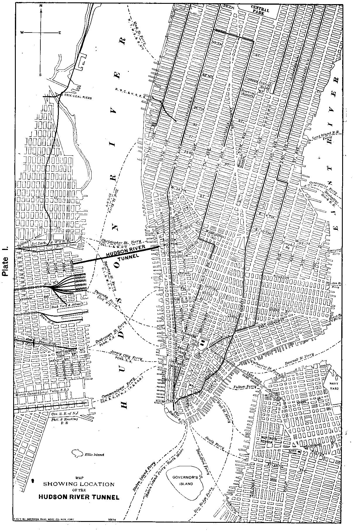
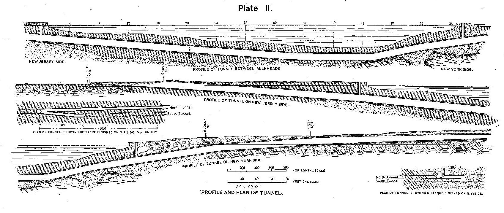
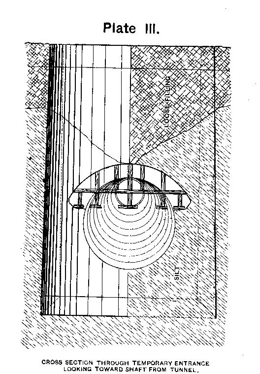
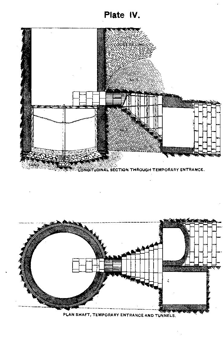
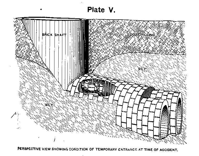
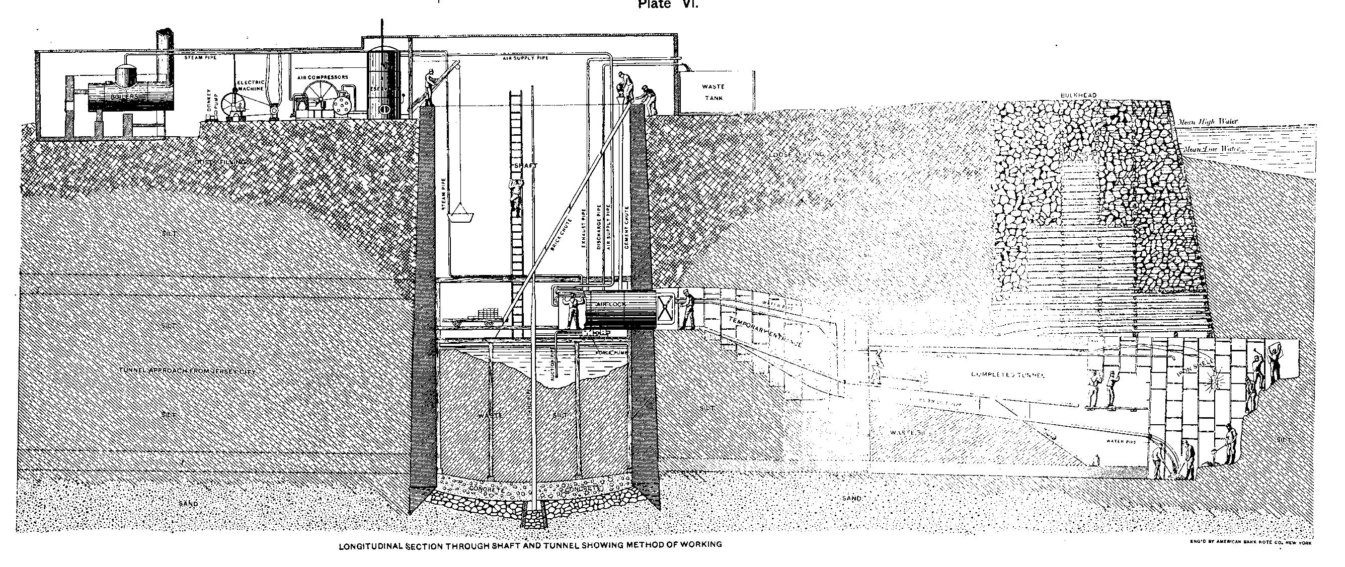
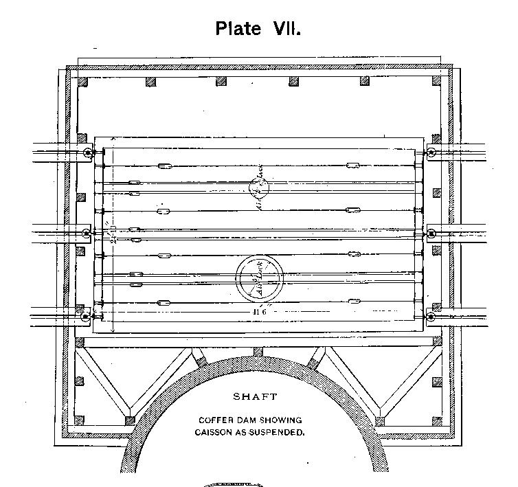
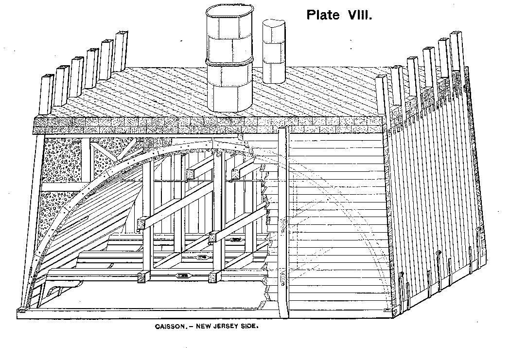
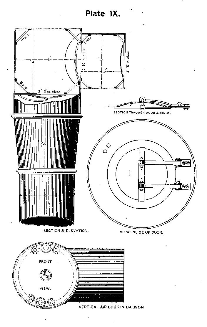
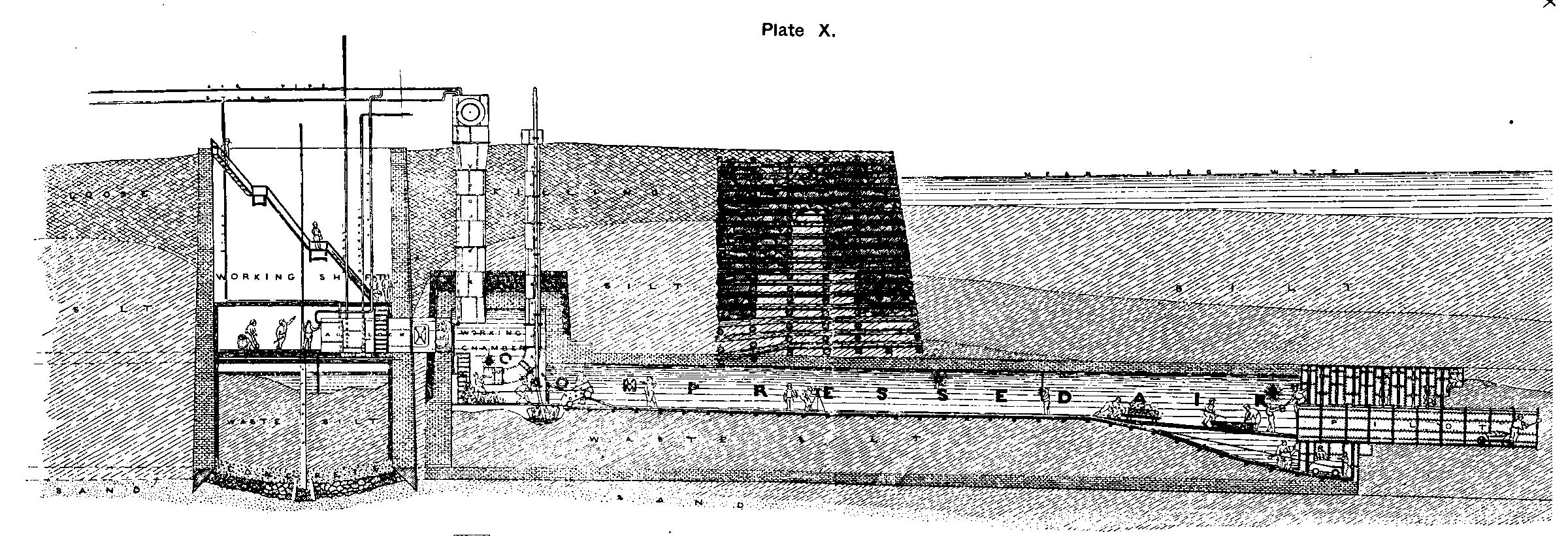
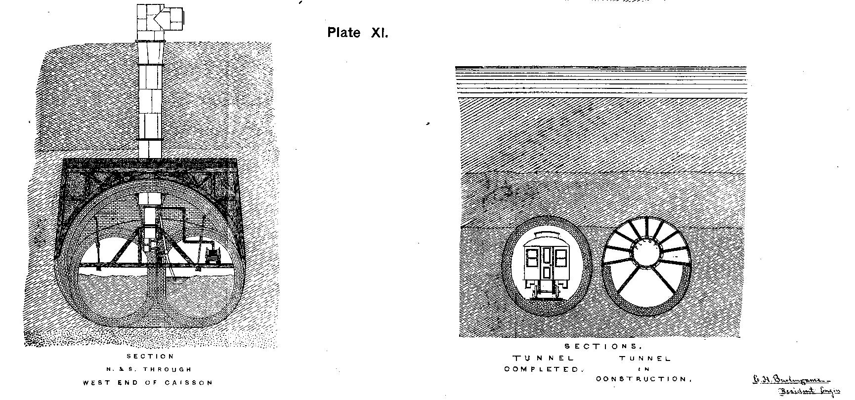
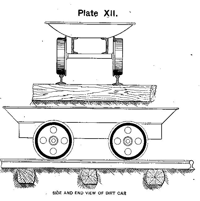
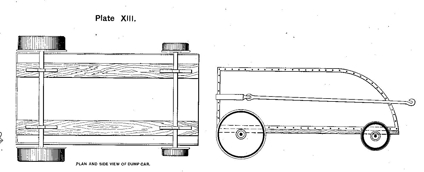
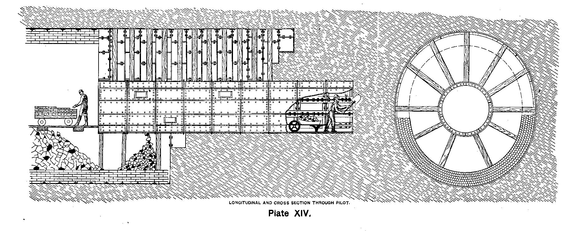
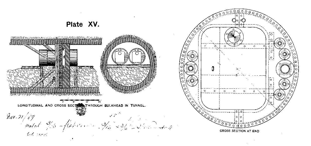
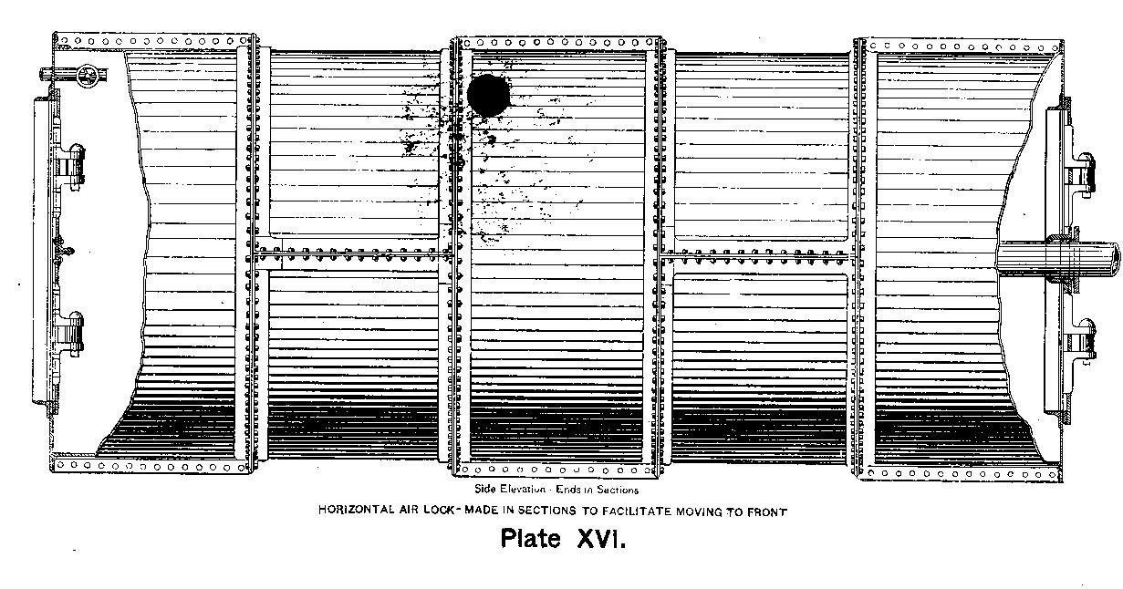
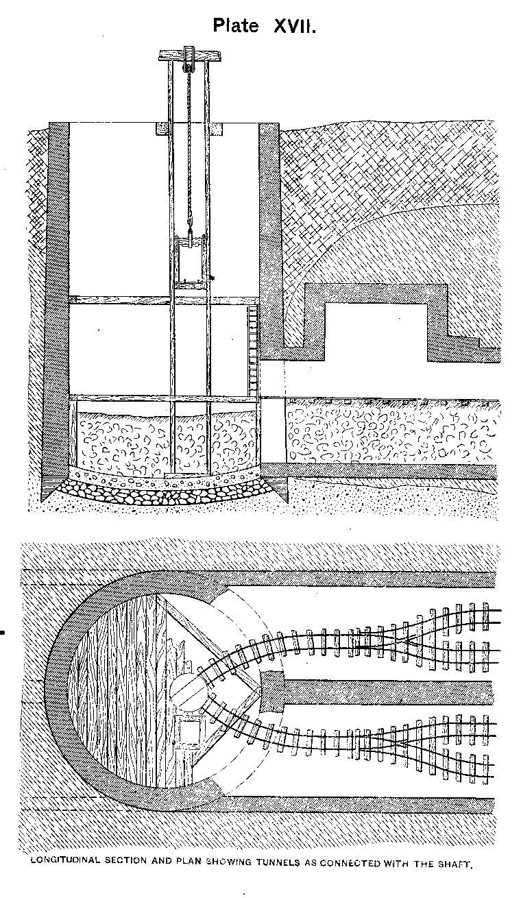
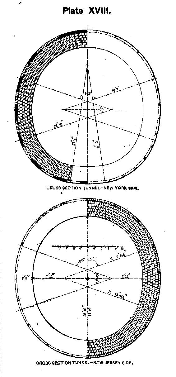
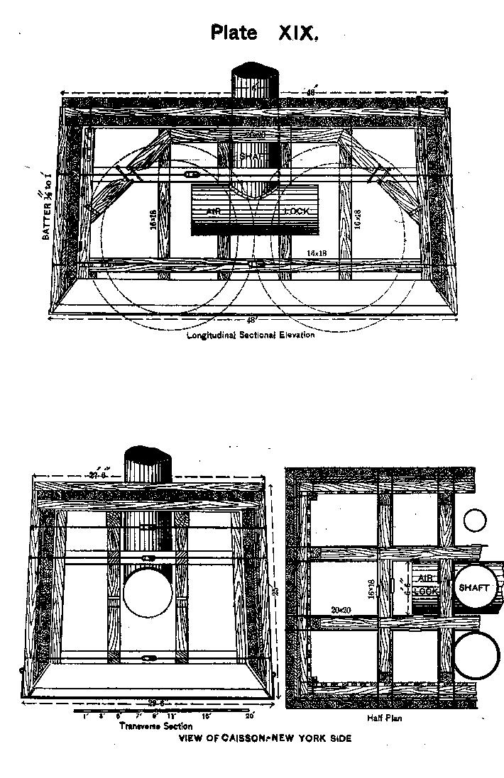
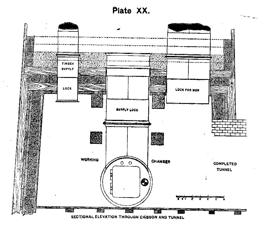
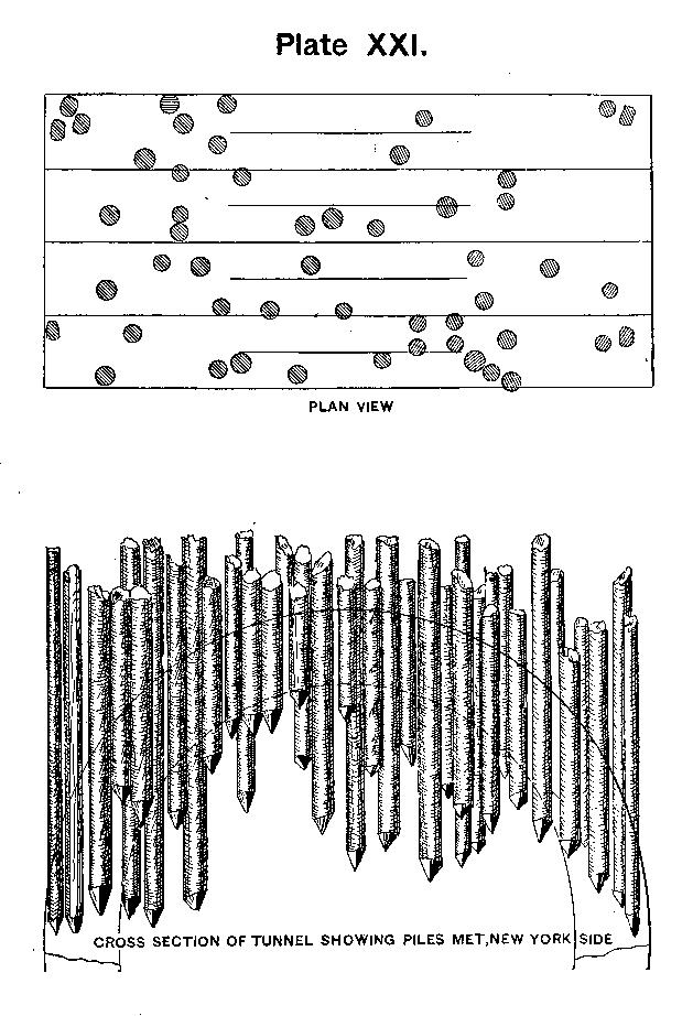
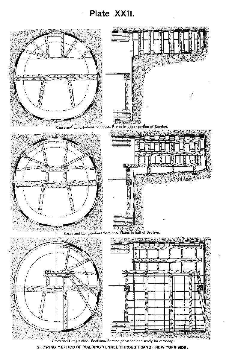
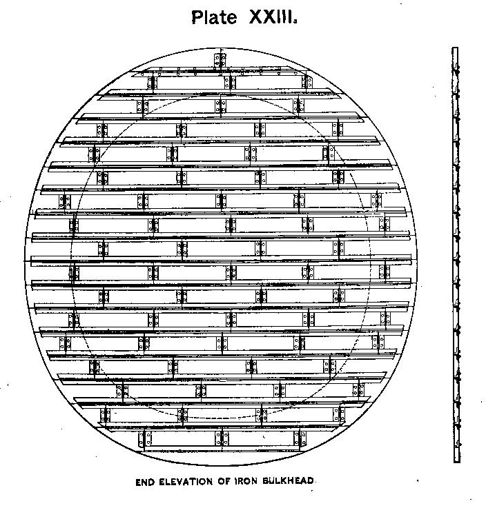
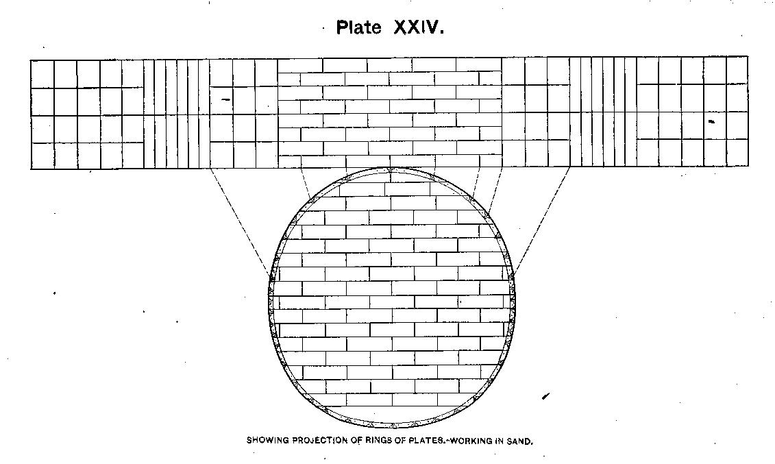
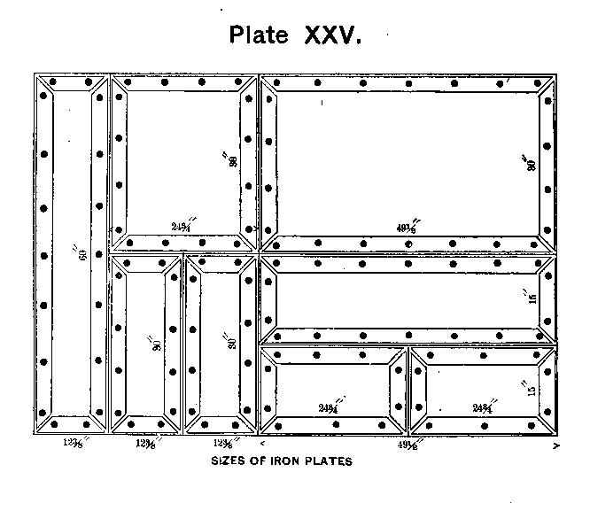
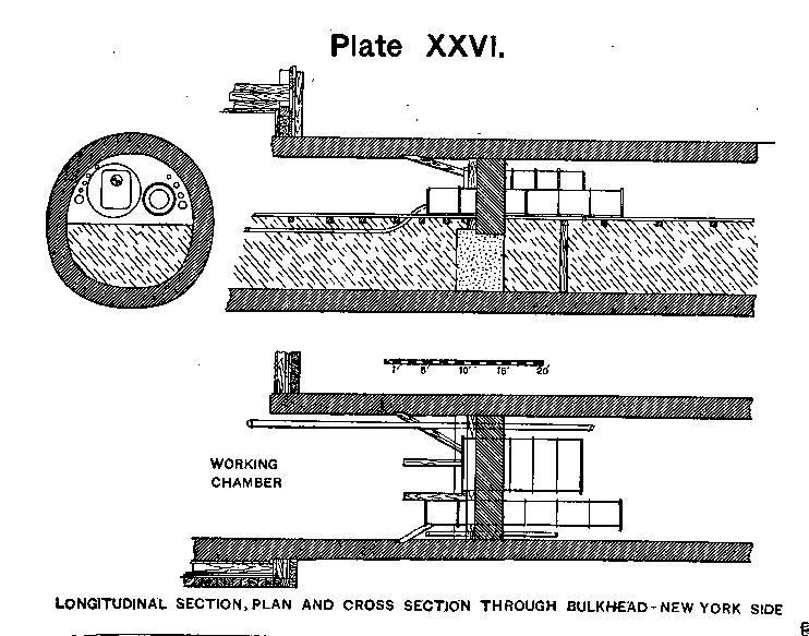
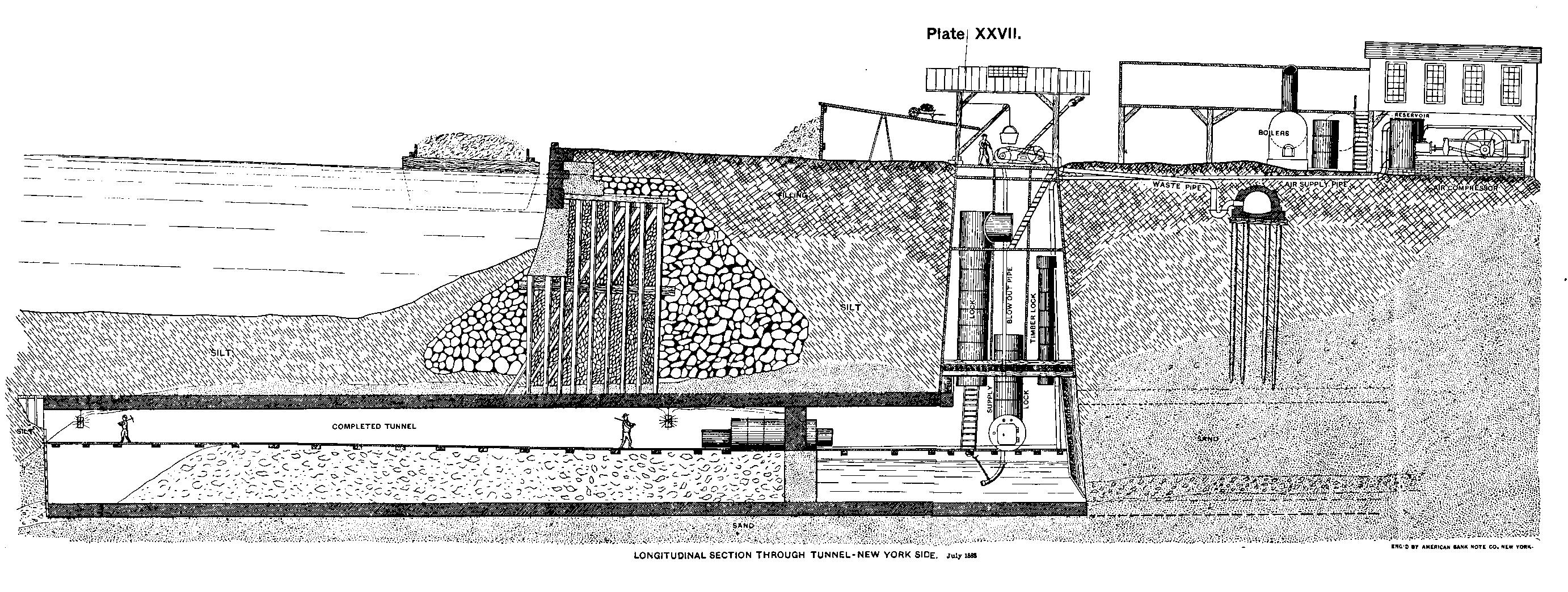
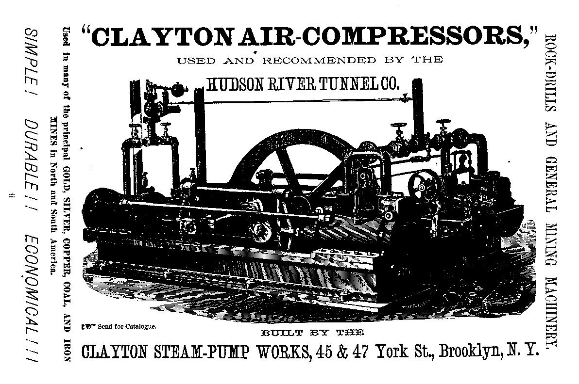
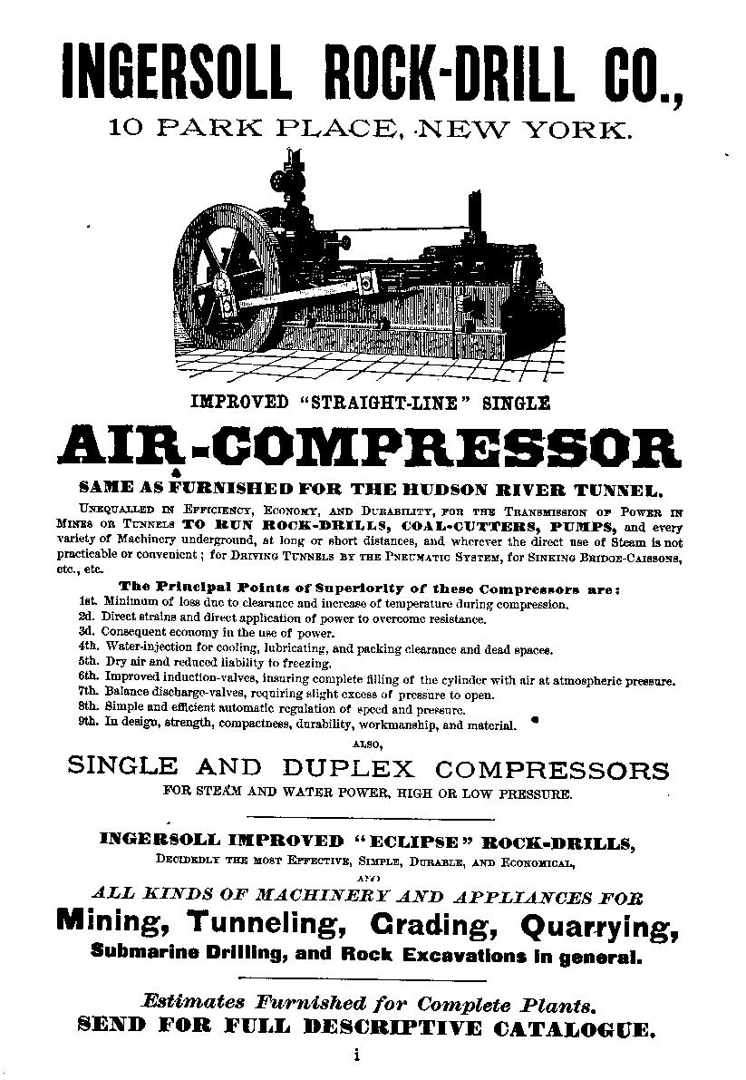